
Apparatus and method for gain-spectrum-tilt compensation in long-wavelength band dispersion-compensating hybrid fiber amplifier

a hybrid fiber amplifier and gain-spectrum tilt compensation technology, applied in the field of optical fiber amplifiers, can solve the problems of deteriorating amplifier signal quality, affecting the performance of amplifiers, and affecting the size of relatively bulky amplifiers, so as to suppress the polarization dependence of raman gain and reduce the degree of pumping light. polarization

Inactive Publication Date: 2006-01-31
ELECTRONICS & TELECOMM RES INST
View PDF5 Cites 1 Cited by
  • Summary
  • Abstract
  • Description
  • Claims
  • Application Information

AI Technical Summary

Benefits of technology

[0012]In an embodiment of the present invention, the apparatus may further include at least one means to reduce the degree of polarization of the pumping light. This can be done, for example, by the use of a depolarizer or a polarization-beam combiner. Both can suppress the polarization dependence of the Raman gain in the DCF.
[0013]In addition, the present invention provides a method of compensating for the variation of the gain spectrum due to the temperature variation of the optical fiber amplifier that has a two-stage structure, which includes the steps of detecting the temperature of the first and second amplification stages, controlling the optical power of pumping light inputted to the DCF located between them, and thereby controlling the Raman gain.
[0015]Additionally, the step of controlling the intensity of the pumping light may includes the step of reducing the degree of polarization of the pumping light of a wavelength of 1500±10 nm inputted to the DCF.

Problems solved by technology

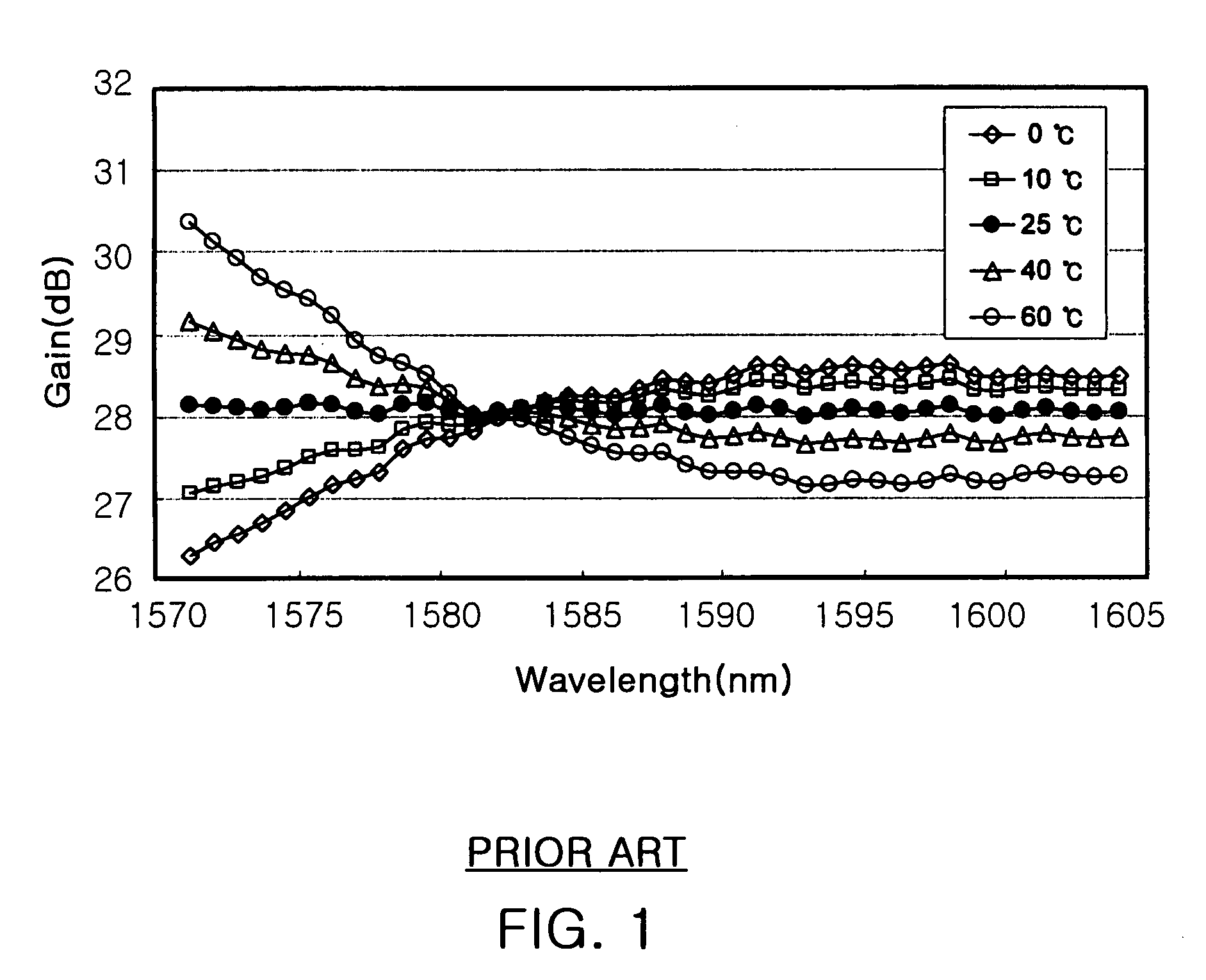
However, the amplified signal qualities deteriorate due to the noises, mainly amplified spontaneous emission (ASE) noise.
However, since this method needs thermal insulation, the complete EDFA module has to become more bulky, which is against the current tendency for compact size.
However, the size problem of a relatively bulky amplifier still remains.
On the other hands, the methods of the parameter control cannot be directly applied to the DCHFA since it has the pumped DCF section where the Raman amplification process occurs.

Method used


Image

  • Apparatus and method for gain-spectrum-tilt compensation in long-wavelength band dispersion-compensating hybrid fiber amplifier
  • Apparatus and method for gain-spectrum-tilt compensation in long-wavelength band dispersion-compensating hybrid fiber amplifier
  • Apparatus and method for gain-spectrum-tilt compensation in long-wavelength band dispersion-compensating hybrid fiber amplifier

Examples


Embodiment Construction

[0027]Reference now should be made to the drawings, in which the same reference numerals are used throughout the different drawings to designate the same or similar components.

[0028]A preferred embodiment of the present invention is described in detail with reference to the accompanying drawings.

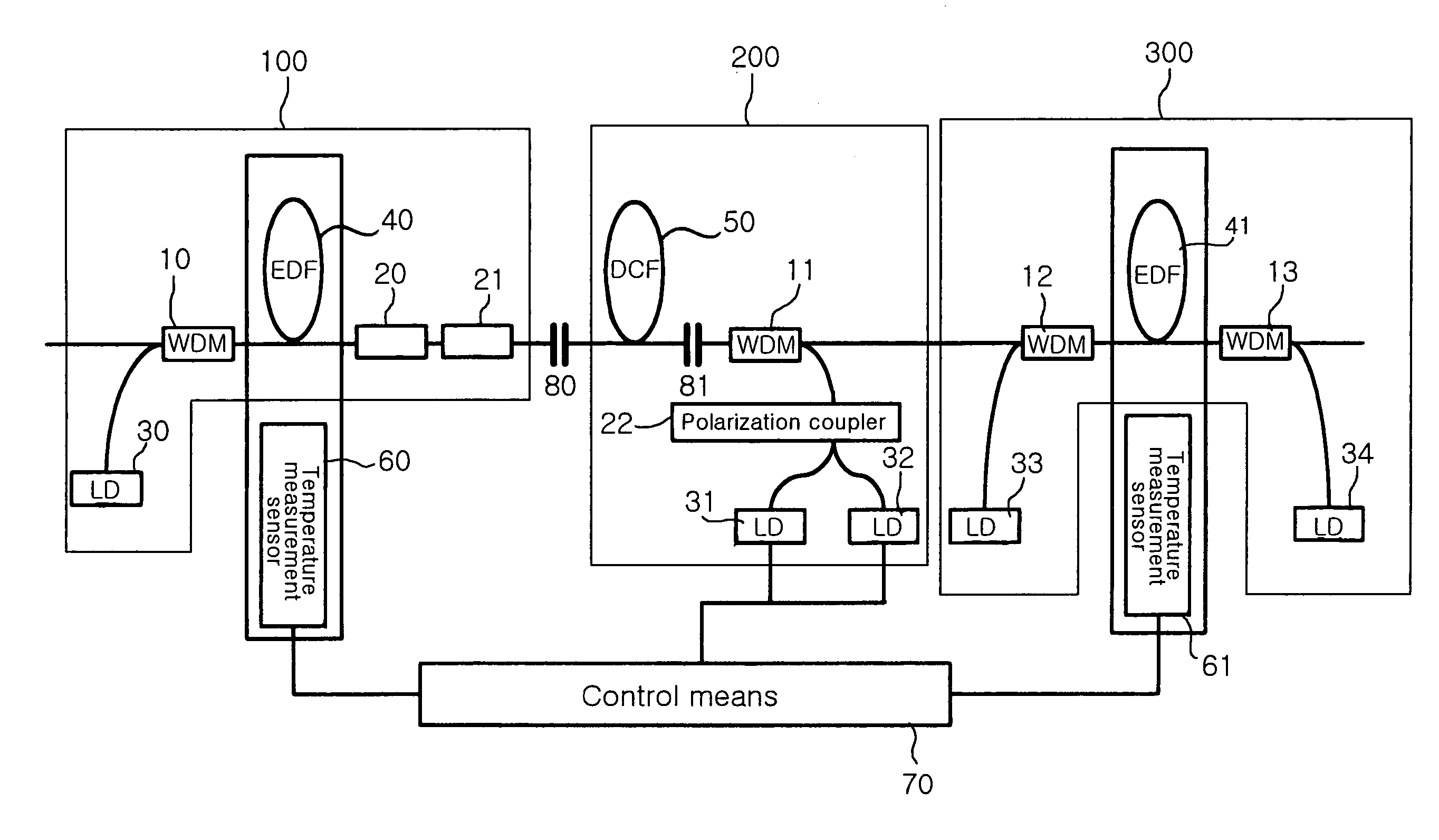
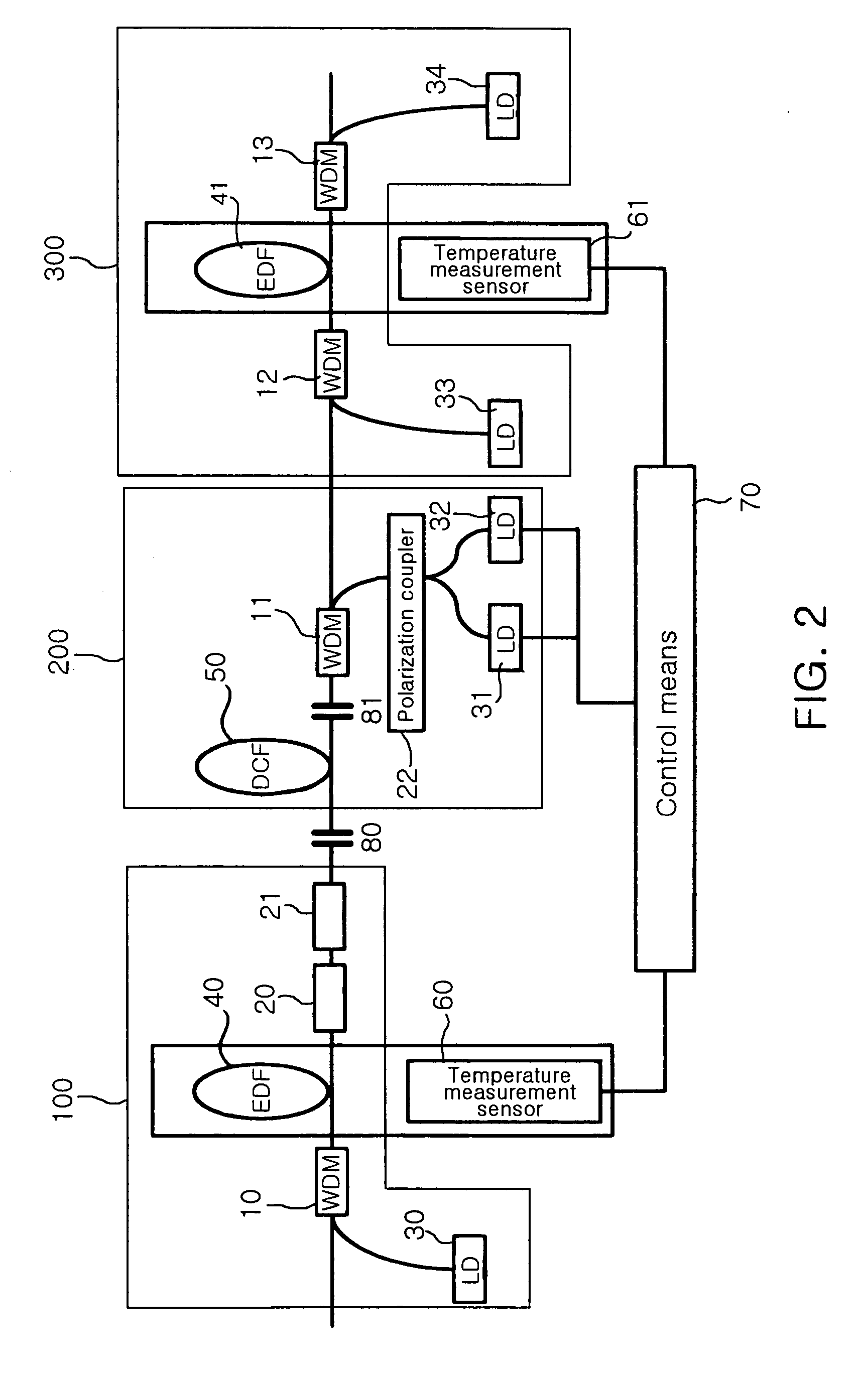
[0029]FIG. 2 is a configuration diagram of an L-band DCHFA equipped with a gain-tilt compensating apparatus in accordance with an embodiment of the present invention. The configuration shown in the drawing is an example of the gain-tilt compensating apparatus applied to an optical fiber amplifier and the L-band DCHFA equipped with the gain-tilt compensating apparatus. Reference numerals 10 to 13 designate wavelength-division multiplexers (WDMs), which combine the L-band optical signals and pumping light into a single optical fiber. In this case, reference numeral 10 preferably designates a WDM that combines 980-nm pumping light with the L-band signals and reference numerals 11 to 13 preferab...


PUM


Abstract

The present invention provides an apparatus and method for compensating for the variation of a gain spectrum attributable to the temperature variation of a fiber amplifier, and a long-wavelength band dispersion-compensating hybrid amplifier equipped with the gain spectrum compensating apparatus. The apparatus includes a DCF located between a first amplification stage and a second amplification stage to compensate for dispersion of an optical signal output from the first amplification stage and perform Raman amplification of the optical signal using input pumping light; at least one pumping light provision means for providing forward or backward pumping light to the DCF; first and second temperature detection means for detecting temperature variations of the first and second amplification stages, respectively; and control means for controlling intensity of the pumping light of the pumping light provision means according to the detected temperature variations.

Description

BACKGROUND OF THE INVENTION[0001]1. Field of the Invention[0002]The present invention is related to the optical fiber amplifiers used in the optical communication systems and, more specifically, to an apparatus and method for compensating for the gain-spectrum-tilt of a long-wavelength band dispersion-compensating hybrid amplifier due to an environmental temperature change, and a long-wavelength band dispersion-compensating hybrid fiber amplifier equipped with the gain-spectrum-tilt compensating apparatus.[0003]2. Description of the Prior Art[0004]In the optical communication using wavelength-division multiplexed (WDM) systems, a plurality of channels are transmitted simultaneously; the conventional band (C-band) of 1530 to 1565 nm, the long-wavelength band (L-band) of 1570 to 1605 nm, or both of them are normally used. In these systems, the optical signals become small through the transmission fibers and recover their launching powers by the optical amplifiers at the end of each sp...

Claims


Application Information

Patent Timeline
Patent Type & Authority Patents(United States)
IPC IPC(8): H01S3/00H01S3/067H01S3/131H01S3/30
CPCH01S3/06758H01S3/1301H01S2301/04H01S3/302H01S3/1608H01S3/10013H01S3/13013H01S3/00
Inventor CHUNG, HEE SANGLEE, WON KYOUNGCHANG, SUN HYOKLEE, HYUN JAECHU, MOO JUNGLEE, HAN HYUBLEE, DONG HANLEE, YONG BAE
Owner ELECTRONICS & TELECOMM RES INST
Learn More