
Apparatus for interfacing electronic packages and test equipment

a technology for interfacing electronic packages and test equipment, which is applied in the direction of coupling device connections, semiconductor/solid-state device testing/measurement, instruments, etc., can solve the problems of compromising the fidelity of electrical signals, affecting the height of interface equipment, and affecting the reliability of electrical signals

Inactive Publication Date: 2006-01-31
RIKA ELECTRONICS INT
View PDF124 Cites 58 Cited by
  • Summary
  • Abstract
  • Description
  • Claims
  • Application Information

AI Technical Summary

Benefits of technology

"The present patent is about an apparatus that interfaces electronic packages and test equipment for the packages. The apparatus includes a printed circuit board with vias and a test socket with plates and bores corresponding to the vias. A conductive sleeve member is positioned in each via with a biasing member and a plunger. The plunger has a cylindrical body with an upper and lower rod portion that makes electrical contact with a package terminal. The apparatus allows for easy testing and interfacing of electronic packages."

Problems solved by technology

This arrangement facilitates testing providing top loading and unloading and is readily adapted for use with different ICs; however, it does have certain limitations.
One such limitation relates to the height required for the interface equipment, i.e., the sockets.
The fidelity of the electrical signal is subject to compromise in that distance having largely uncontrolled impedance and high cross talk.

Method used


Image

  • Apparatus for interfacing electronic packages and test equipment
  • Apparatus for interfacing electronic packages and test equipment
  • Apparatus for interfacing electronic packages and test equipment

Examples


Embodiment Construction

[0030]The present disclosure is directed to an apparatus for maximizing the fidelity of an electrical signal passing from test equipment to an IC package or device under test (hereinafter (DUT), by reducing the distance between the test equipment and the terminals of the DUT. The apparatus includes a test socket for holding the DUT, which is mounted on a printed circuit board (hereinafter “DUT board”) in a conventional manner. The DUT board contains a plurality of bores in which contact probe assemblies are received and which form interconnects between the test equipment and the DUT.

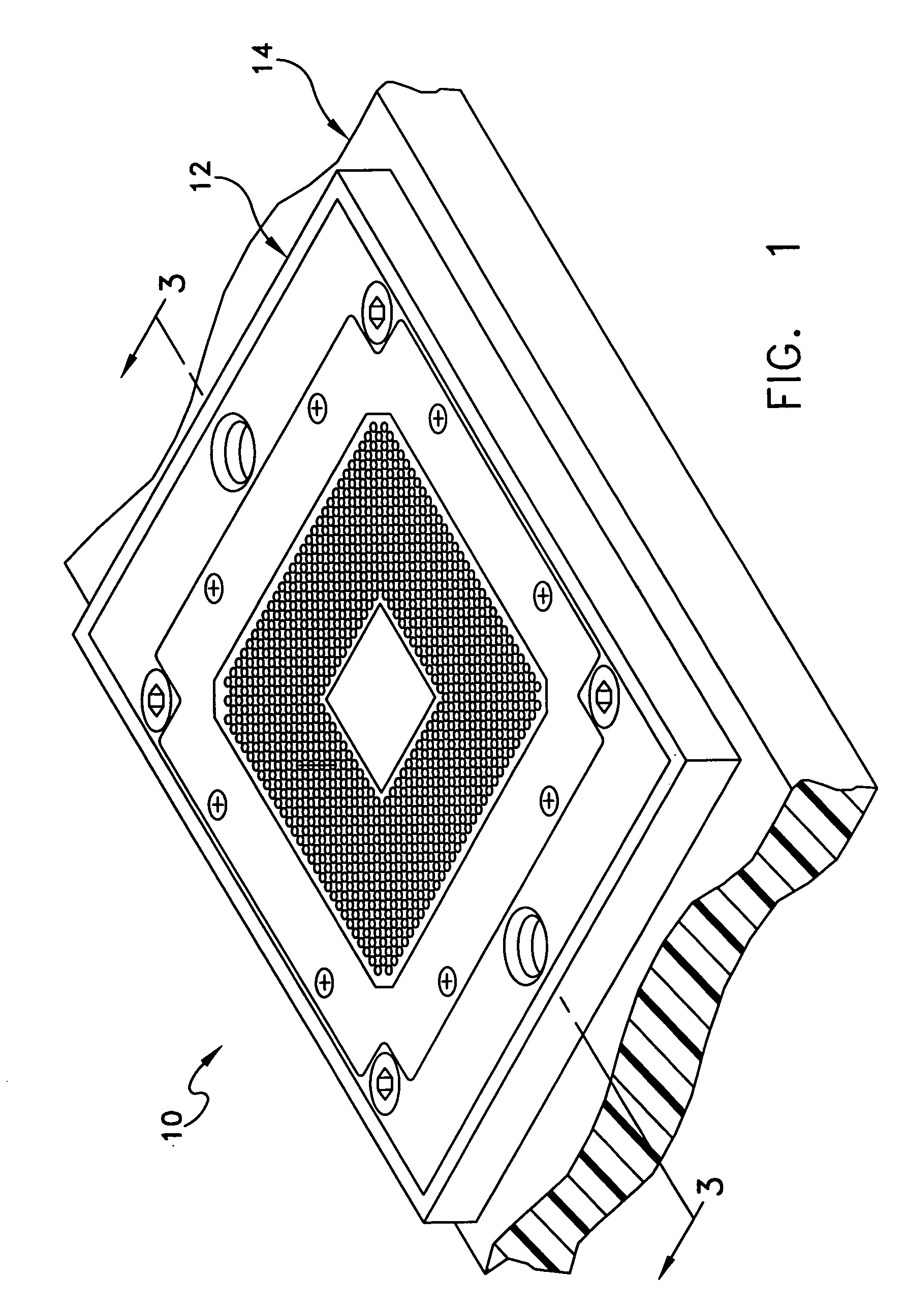
[0031]FIGS. 1–8, when taken together, illustrate one embodiment of an apparatus 10 according to the present disclosure. As shown in FIGS. 1–3, apparatus 10 includes test socket 12 mounted on a DUT board 14 in a conventional manner. A electronic or IC package (hereinafter package) 16, which in the present embodiment is a PGA package carrying a DUT (not illustrated), is mounted in test socket 12 in a conve...


PUM


Abstract

A test apparatus for testing electrical devices such as ICs is provided. The test apparatus includes a test socket mounted on a DUT board in which a contact plunger assembly is at least partially positioned.

Description

RELATED APPLICATIONS[0001]Priority is hereby claimed under 35 U.S.C. § 119(e) to co-pending and commonly-owned U.S. Provisional Patent Application No. 60 / 361882, which was filed on Mar. 5, 2002, and U.S. Provisional Patent Application No. 60 / 410121, which was filed on Sep. 13, 2002, each of which is incorporated herein by reference in its entirety.BACKGROUND[0002]1. Technical Field[0003]This disclosure relates generally to equipment used in testing electronic packages, such as integrated circuits, and more particularly to an apparatus for interfacing electronic packages and test equipment.[0004]2. Related Art[0005]Typically, integrated circuit (IC) packages (devices under test) are removably mounted in sockets which in turn are mounted on a circuit substrate, commonly referred to as a device-under-test or DUT board. The sockets mount individual contacts for electrically connecting each terminal of a device to be tested to an individual circuit path on the DUT board. The DUT board is...

Claims


Application Information

Patent Timeline
Patent Type & Authority Patents(United States)
IPC IPC(8): G01R31/02G01R1/04G01R31/26G01R1/067G01R1/073H01R13/24H01R33/76
CPCG01R1/0441G01R1/07314G01R1/06722G01R31/26H01L22/00
Inventor WINTER, JOHN M.NELSON, LARRE H.BERGERON, JOHN C.SARCIONE, LOURIE M.
Owner RIKA ELECTRONICS INT
Learn More