
Electrical component of a motor vehicle

a technology of electrical components and motor vehicles, which is applied in the direction of coupling device details, coupling device connections, electric discharge lamps, etc., can solve the problems of reduced cabling cost and control complexity, disadvantages of general required diversity of versions in regard to the producibility of electrical components, and low cost of cabling between the control and the actuator or sensor, etc., to achieve simple parameterization of electrical components and easy production

Inactive Publication Date: 2006-01-31
BROSE SCHLIESSSYSTEME GMBH & CO KG
View PDF11 Cites 1 Cited by
  • Summary
  • Abstract
  • Description
  • Claims
  • Application Information

AI Technical Summary

Benefits of technology

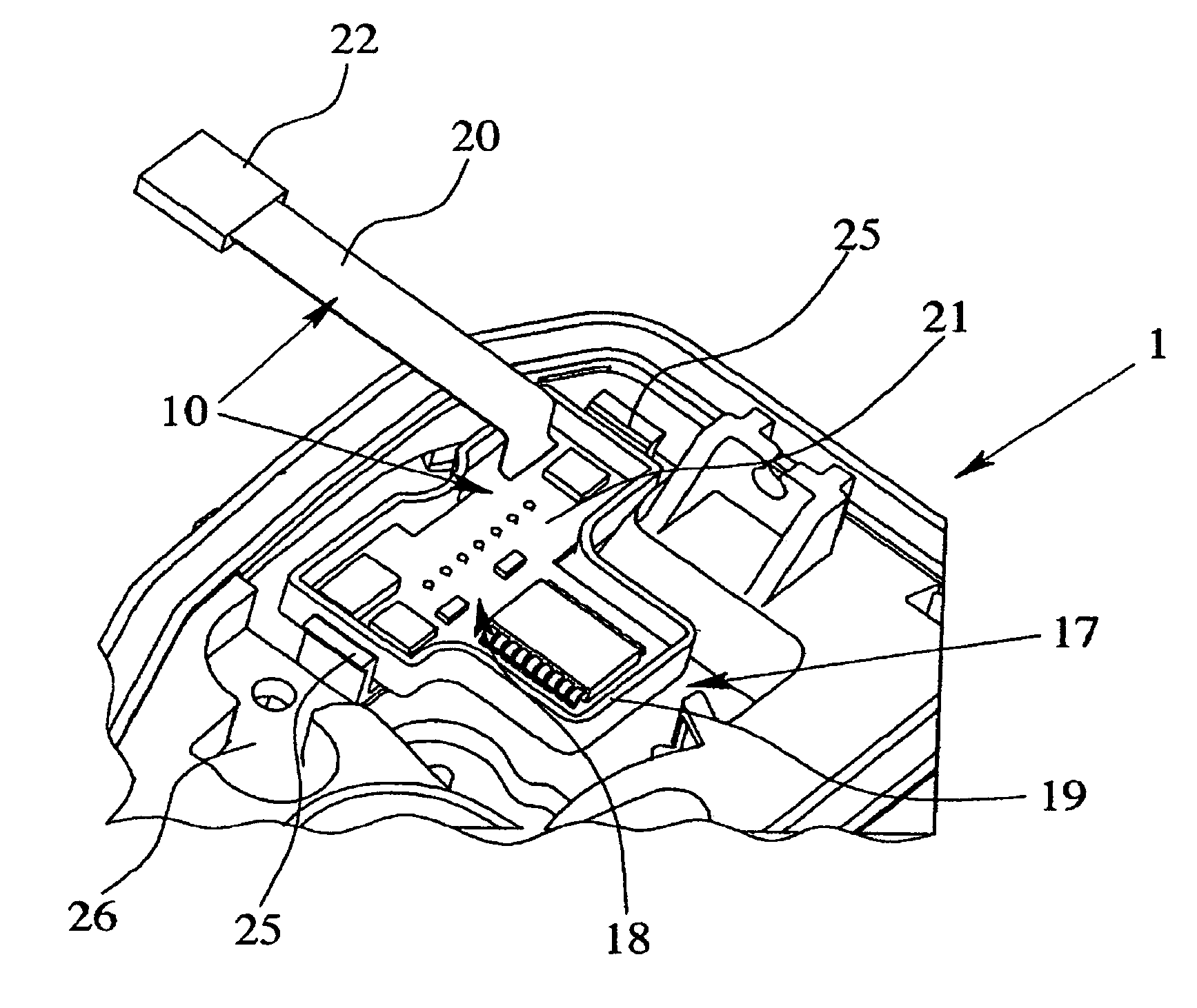
The present invention is about a new electrical component for a motor vehicle that allows for a decentralized control concept that is optimized both for production engineering and later maintenance work. The electrical component includes control electronics and a plug-and-socket connection for electrical connection to another electrical component or control. The control electronics are detachably connectable to the plug-and-socket connection, which can be easily replaced without changing the electrical component. This allows for easy production and interchangeability of the control electronics, as well as simple parameterization and retrofitting. The invention also provides flexibility in the parameterization of the electrical component and reduces the need for costly measures related to control electronics in the production line.

Problems solved by technology

The cost of the cabling between the control and the actuator or sensors and between the control and the outside door handles is considerable.
While the cabling cost and the complexity of the control are reduced overall with the aforementioned decentralization, disadvantages arise with respect to the generally required diversity of versions with regard to the producibility of the electrical components.
Furthermore, by integration of the control electronics into the electrical component, the complexity of production is increased since expensive measures must be provided in the production line to protect sensitive electronic components.
Finally, when the control electronics which have been integrated into the electrical component fail, replacing the entire electrical component is usually not avoided, thereby leading to high costs.

Method used


Image

  • Electrical component of a motor vehicle
  • Electrical component of a motor vehicle
  • Electrical component of a motor vehicle

Examples


Embodiment Construction

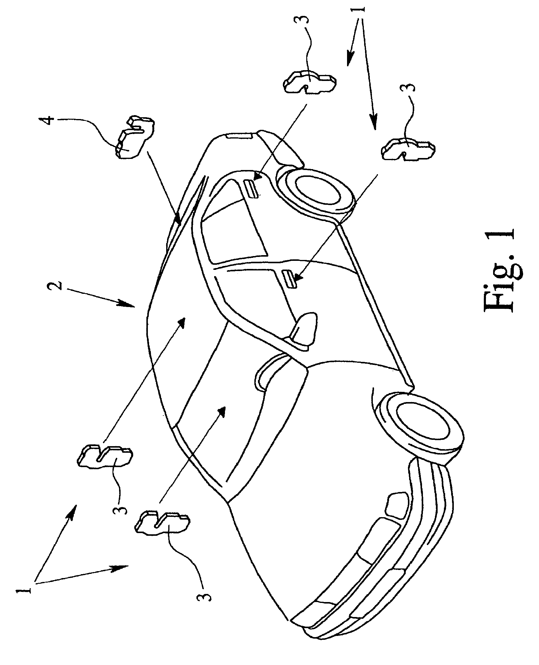
[0027]In the drawings, FIG. 1 shows a motor vehicle 2 which is made with electrical components 1 of a motor vehicle door locking system. It should be pointed out that an electrical component here is defined as any electrically actuated functional unit of a motor vehicle. The electrical components 1 can include several motor vehicle door locks 3 and a hood lock 4, with installation positions shown schematically in FIG. 1. The motor vehicle door locks 3 can be locked and unlocked by a motor in the sense of a central interlock. Each motor vehicle lock 3, embodied as an electrical lock, also has the possibility of motorized opening. The lifting of a ratchet by means of an opening drive is not shown.

[0028]It is pointed out that the proposed approach is described below using electrical components of a motor vehicle door locking system as an example. But this is not to be understood restrictively. All conceivable electrical components 1 of a motor vehicle 2 are considered to be an electric...


PUM


Abstract

This invention relates to an electrical component of a motor vehicle, the electrical component. The electrical component includes control electronics and at least one plug-and-socket connection for electrical connection of the electrical component to a coordinating control or another electrical component. The plug and socket connection further includes a plug, a plug housing and a connecting line. The plug-and-socket connection is detachably connectable, on one end, to a plug receptacle and wherein at least part of the control electronics is housed in the plug-and-socket connection.

Description

BACKGROUND OF THE INVENTION[0001]1. Field of the Invention[0002]The invention relates to an electrical component of a motor vehicle, and more specifically, to a plug-and-socket connection of an electrical component of a motor vehicle.[0003]2. Description of Related Art[0004]Electrical components of a motor vehicle enable increasingly more complex electrically actuated functions. One example is a motor vehicle door lock which is an electrical lock discussed in published German Patent Application DE 195 45 722 A1 which, in addition to conventional locking functions, enables motorized lifting of the ratchet. The coordination of these functions is assumed by a central control. The cost of the cabling between the control and the actuator or sensors and between the control and the outside door handles is considerable.[0005]In order to make the described complexity of the electrical components managable, both with respect to the scope of operation and also with respect to the resulting cab...

Claims


Application Information

Patent Timeline
Patent Type & Authority Patents(United States)
IPC IPC(8): H01R12/00H05K1/00H01R13/66H01R31/06H01R33/945
CPCH01R31/065H01R13/665Y10S439/949H01R2201/20H01R2201/26H01R33/945
Inventor KOERWER, MATTHIASHENTSCH, INGMARHEGERFELD, FRANK
Owner BROSE SCHLIESSSYSTEME GMBH & CO KG
Learn More