
LED curing light

a curing light and led technology, applied in boring tools, dental tools, dental prosthetics, etc., can solve the problems of high light beam divergence, low light output intensity, and low light output intensity of led curing lights

Inactive Publication Date: 2006-01-31
TSIMERMAN EFRAIM +1
View PDF9 Cites 57 Cited by
  • Summary
  • Abstract
  • Description
  • Claims
  • Application Information

AI Technical Summary

Benefits of technology

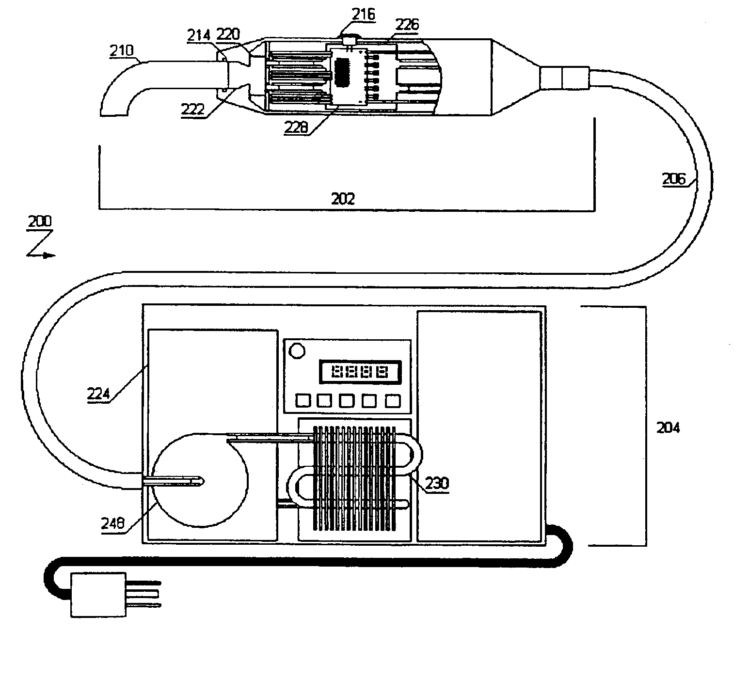
[0011]In accordance with another aspect of the invention, the curing light may be a combination of a base station and a hand held unit interconnected by a supply conduit. Alternatively, the curing light may include a base station and a...

Problems solved by technology

One of the problems with LED curing lights however is that their light output intensity is relatively low.
Because of the low output, LED curing lights are at a disadvantage in the speed of cure as compared with more intense light sources such as halogen bulbs, plasma arc or xenon light sources.
One of the problems of these types of LEDs is that their light beam is highly divergent, often as much as 160°.
This in turn means that much of the light, perhaps as much as 70% will be lost if the LED is coupled directly to a fibreoptic light guide with a typical numerical aperture of 0.5.
A 0.5 numerical aperture means that all rays with a divergence of greater than 30° will not be accepted into the light guide and therefore will be ineffective.
On the other hand, if used without a light guide, that is, directly at the surface contacting the tooth, it is still not possible to productively use more than one LED of this type because the dimensions of the typical tooth involved would still not be greater than 11×10 mm.
However in this case, the light beam becomes even more divergent, typically about 180° and the heat generated from a high number of such dies within the device may create difficulty with respect to cooling.

Method used


Image

  • LED curing light
  • LED curing light
  • LED curing light

Examples


Embodiment Construction

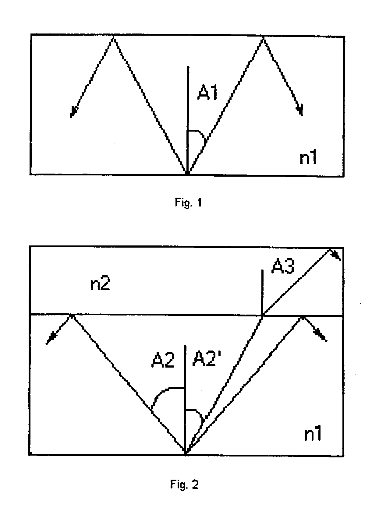
[0034]In order to more clearly understand the effect of the light output of LEDs, or a matrix of LEDs, it is first useful to consider the output.

[0035]For the sake of simplicity, the following discussion assumes that the LED light output is a hemispherical shape. The following figures illustrate sections through a cone showing the angles of the rays of emitted light. Accordingly, FIG. 1 indicates that from the total amount of light, originated within an LED, only the portion within the spherical angle of + / − A1 as shown in FIG. 1 can escape into the ambient air through the light emitting surface (hereinafter referred to as the forward facing surface) of the die. The value of the angle A1 is given by the equation: sin⁡(A1)=1n1(1)

where n1 is the index of refraction of the material of the LED die.

[0036]The efficiency of light extraction is given by the equation:

Ef=1−cos(A1)   (2)

In the case of blue LEDs, n1=2.4. A1 is about 25° and the Ef=9.4%. If the ray from the die escapes into a ma...


PUM


Abstract

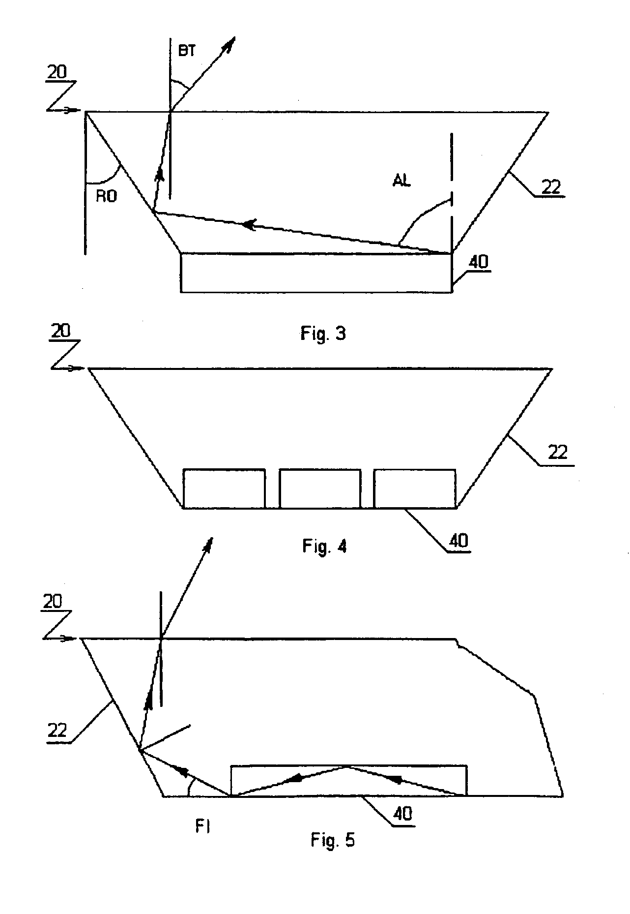
A light source which may be used as part of a dental curing lamp is comprised of at least one, and preferably a plurality, of LEDs. To increase the efficiency of the light output the LEDs are encapsulated in a beam converger including an extractor portion and a collimator portion. Light rays leaving the collimator portion have an angle which matches the entrance angle input requirements of an associated light guide. In another aspect, cooling of LEDs is accomplished by reservoirs located in a hand piece and in a base station. In another aspect of the invention, cooling is achieved by use of a heat pipe and a cooling jacket. The cooling jacket may contain a material having a high latent heat of fusion at a phase change temperature suitable for cooling the LEDs.

Description

FIELD OF THE INVENTION[0001]This invention relates to the field of curing lights and in particular curing lights as used in the field of health care, particularly, within dentistry.BACKGROUND OF THE INVENTION[0002]Curing lights are devices which are used to create a beam of light of an appropriate wavelength to cause curing of photosensitive materials. Various sources of light have been used within curing lights. The source of light may be a halogen bulb, a Xenon bulb, and more recently light emitting devices herein referred to as LEDs.[0003]One of the advantages of using LEDs as the light source arises from the fact that the emission spectrum of some LEDs, in particular, blue LEDs, is in a very narrow band which coincides with the peak of the absorption spectrum of camphorquinone, the most common photoactivator in dental photosensitive materials. Because of the narrow band, almost all of the light energy reaching the material is useful in the process of activating polymerization. N...

Claims


Application Information

Patent Timeline
IPC IPC(8): A61C1/00A61C13/15
CPCA61C19/004H05K1/0203H05K1/0209Y10S362/80H05K2201/10106Y10S362/804
Inventor TSIMERMAN, EFRAIMCHOUSTER, EMIL
Owner TSIMERMAN EFRAIM
Learn More