
Method and apparatus for reaction wheel dynamic compensation in long-duration deployment of a large reflector

Inactive Publication Date: 2006-01-24
THE BOEING CO
View PDF14 Cites 9 Cited by
  • Summary
  • Abstract
  • Description
  • Claims
  • Application Information

AI Technical Summary

Benefits of technology

[0021]The present invention applies two elements (direct solar control and gyroscopic torque due to internal momentum perpendicular to the spacecraft rotational rate) to counter the effects of environmental torques on deployment. Unlike the prior art, the present invention recognizes and takes advantage of the fact the payload is inactive during satellite and appendage deployment. This reduces the power consumption and heat dissipation of the satellite, permitting greater flexibility in the manipulation of the solar arrays (because there is less need to keep the surfaces of the solar arrays directed at the sun and because the thermal radiators remain in the stowed position, permitting greater solar array movement without interference).

Problems solved by technology

However, in some circumstances, the effect of environmental torques and the momentum of the deployed appendage(s) cannot be adequately accommodated by the attitude control system of the satellite.
Communications systems have also been devised to permit worldwide communications to mobile receivers, but such designs have met with limited success.
One of the reasons for this limited success is that it is difficult to design a lightweight, mobile receiver that can communicate with the satellite constellation, even a constellation in mid or low Earth orbits.
The problem with this solution is that to provide high sensitivity over wide beamwidths, the antennas must be quite large.
This raises difficulties in three respects.
First, the larger antennas have larger inertia than the smaller prior art antennas discussed above, thus imposing more stringent requirements on the design of the satellite control system, including the sensors (e.g. star and sun sensors, gyros and accelerometers), the attitude control thrusters, and the algorithms implemented by the control system.
Second, since the larger antenna must be designed to fit within the storage bay of the launch vehicle deploying the satellite, the structures relating to its deployment are typically more complex than those of smaller appendages.
Expressing the dynamics of the deployment of such antennas can be a daunting task, making it difficult for the satellite designer to assure that such deployment does not compromise satellite stability.
However, doing so subjects the satellite and the deployed appendage to a variety of disturbance torques (including solar torques) that further complicate the deployment process.
It is possible, of course, to simply design the attitude control system to permit the rapid deployment of the appendage (e.g. by thruster torques), but such a solution would require a satellite control system that would be far more robust than is required at any time after the appendage is deployed, increasing the weight and cost of the satellite.
Also, using thrusters during deployment raises the possibility that the appendage will be damaged during deployment.
While useful, such techniques are thought to be only applicable in operational, non-spinning satellites with relatively constant mass properties (e.g. not during deployment of a large appendage).
Further, such techniques are limited in application, because the manipulation of the solar arrays can have a deleterious effect on the ability of the solar arrays to generate power for satellite operation.
However, this technique relies on a combination of gyroscopic torque and thruster torque, and, as described above, it is undesirable to use thruster torque during appendage deployment.
However, this technique is not generally applicable to the problem of large appendage deployment, where the dynamic state is expected to be a rotation perpendicular to the pitch axis, at a rotational rate that is typically an order of magnitude higher.

Method used


Image

  • Method and apparatus for reaction wheel dynamic compensation in long-duration deployment of a large reflector
  • Method and apparatus for reaction wheel dynamic compensation in long-duration deployment of a large reflector
  • Method and apparatus for reaction wheel dynamic compensation in long-duration deployment of a large reflector

Examples


Embodiment Construction

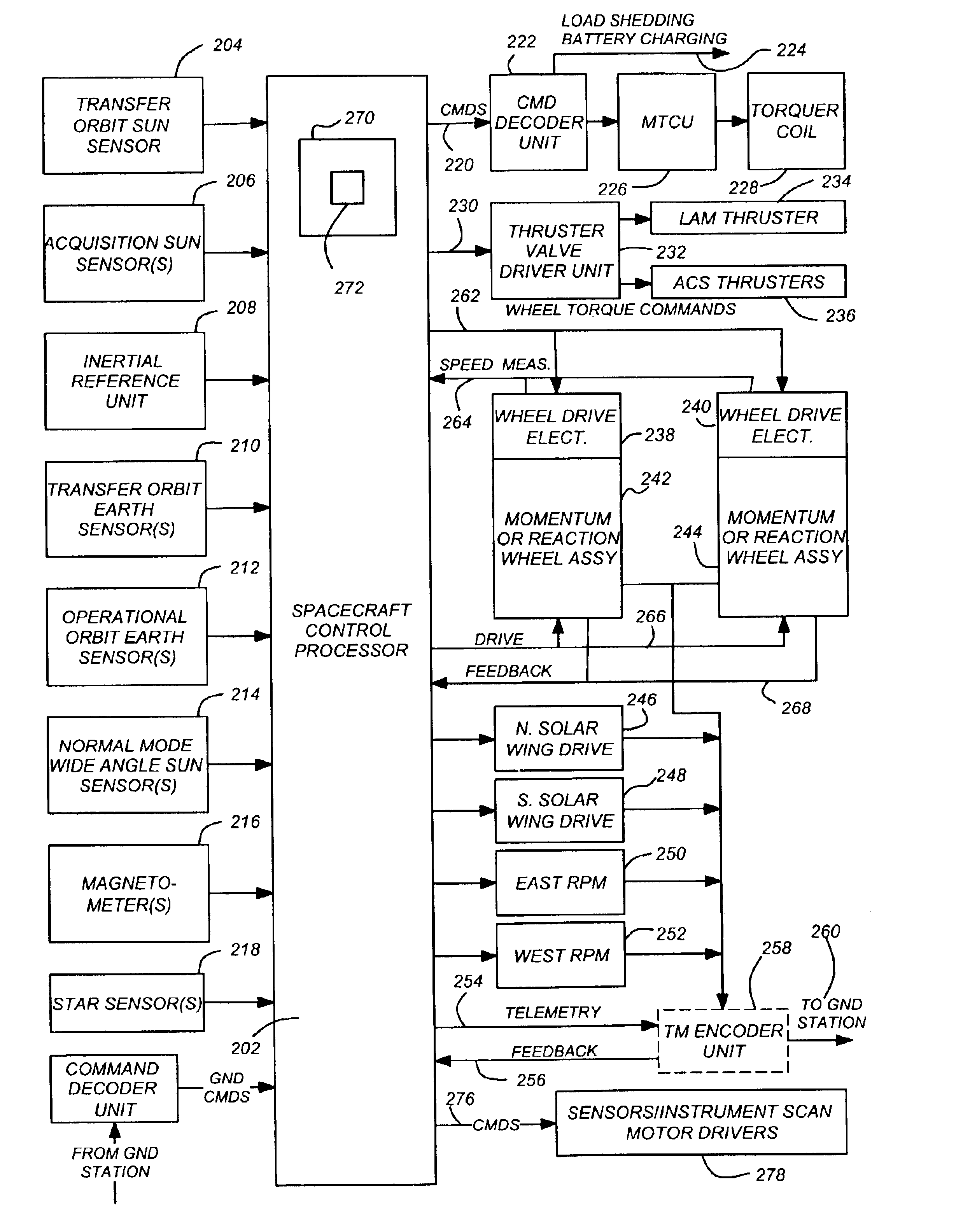
[0032]In the following description, reference is made to the accompanying drawings which form a part hereof, and which is shown, by way of illustration, several embodiments of the present invention. It is understood that other embodiments may be utilized and structural changes may be made without departing from the scope of the present invention.

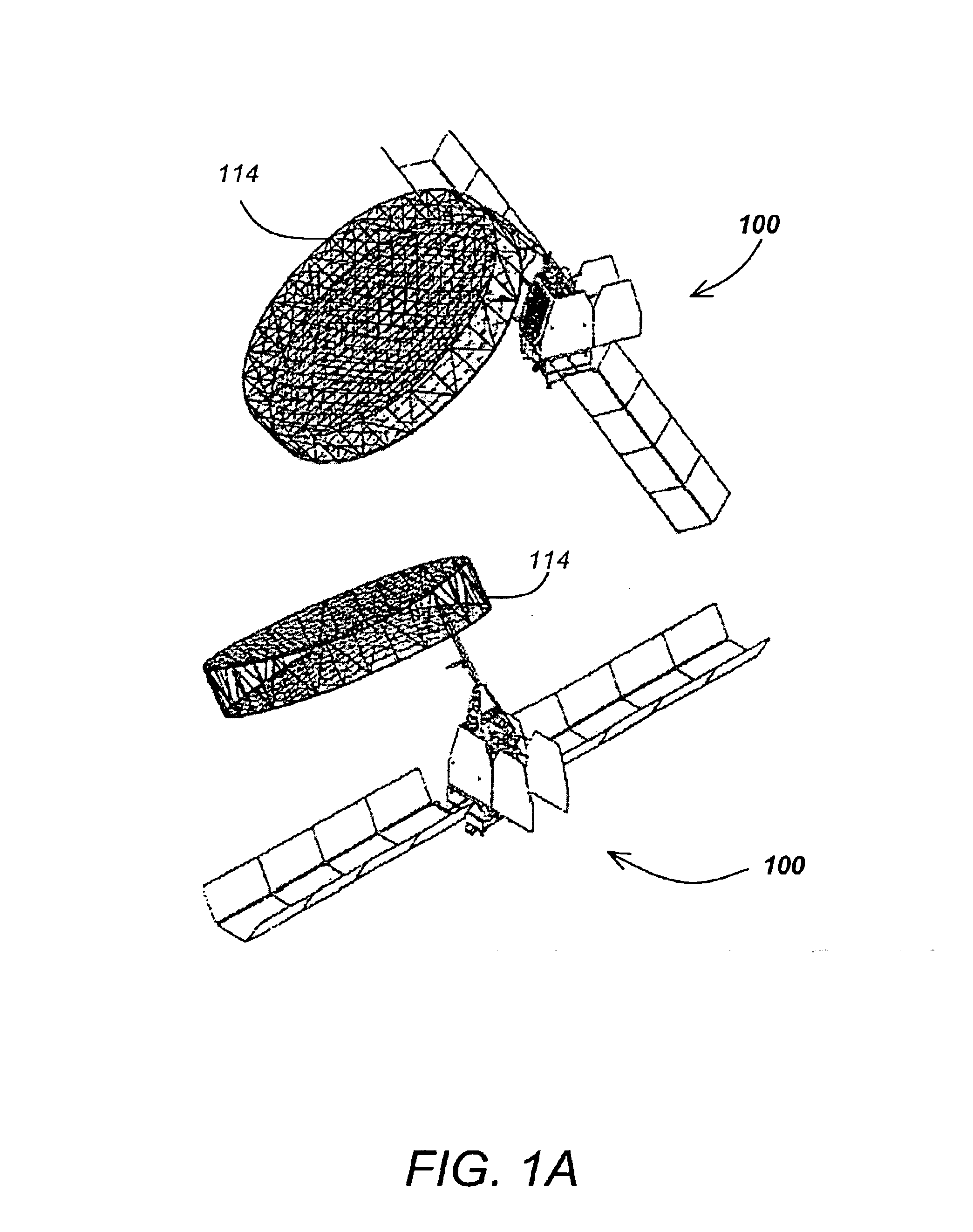
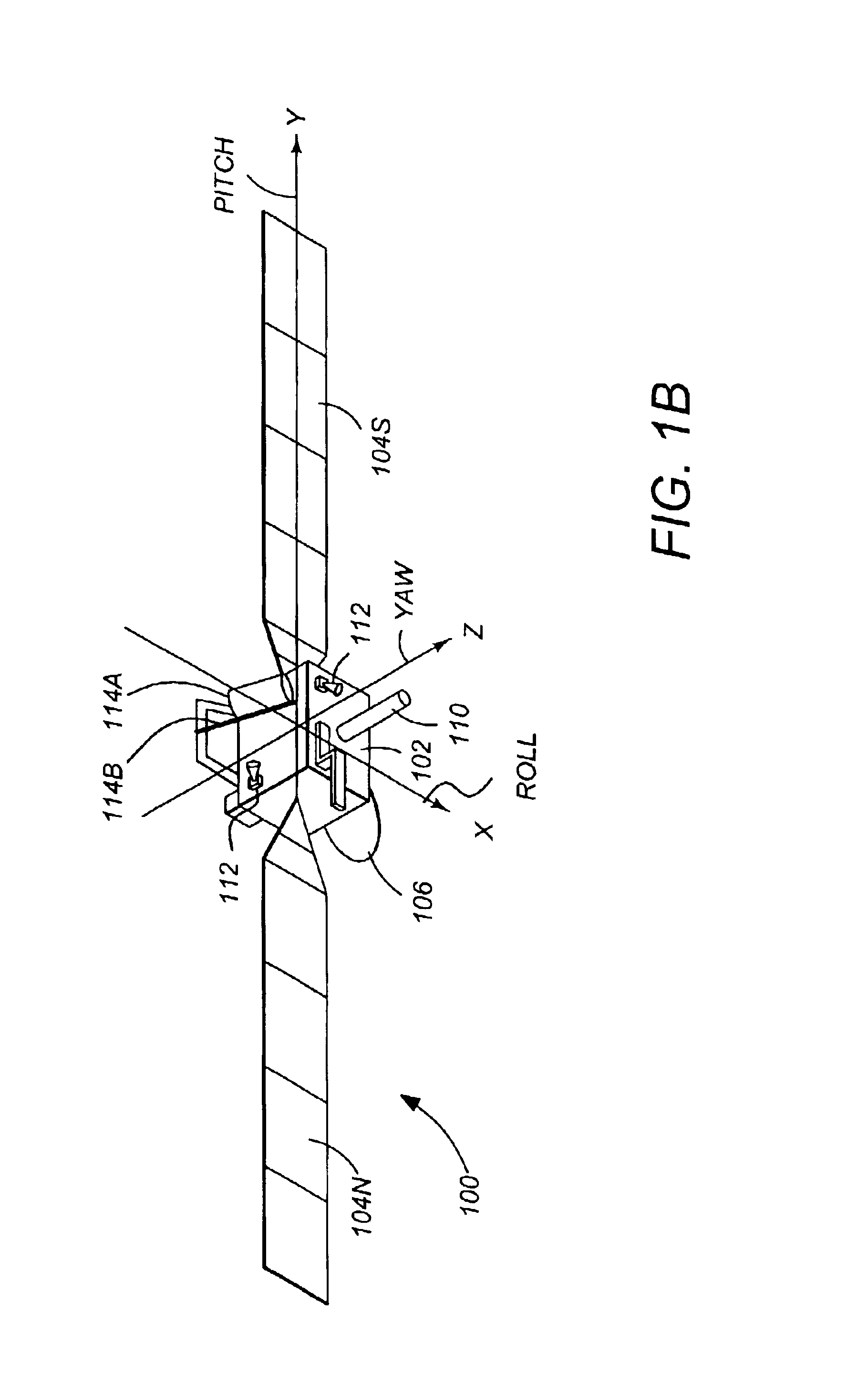
[0033]FIGS. 1A and 1B illustrate a three-axis stabilized satellite or spacecraft 100. FIG. 1A illustrates an appendage 114 in a deployed position, while FIG. 1B illustrates the appendage 114 in a stowed position. The satellite 100 has a main body 102, a pair of solar wings or panels 104N and 104S. The satellite 100 may also have a number of instruments and sensors such as one or more high gain narrow beam antennas 106, a telemetry and command omni-directional antenna which is aimed at a control ground station, a boom-mounted magnetometer, or an optical imager that is aimed at various ground targets.

[0034]The satellite 100 may also include on...


PUM


Abstract

A method and an apparatus for controlling the attitude and momentum of a spacecraft while deploying an appendage from the spacecraft. The method comprises the steps of predicting an environmental torque the spacecraft will be subjected to during deployment of the appendage, computing a magnitude and a direction of momentum to add to the spacecraft to at least partially oppose the predicted environmental torque, and storing the computed magnitude and direction of momentum in at least one of the momentum wheels before deploying the appendage.

Description

CROSS-REFERENCE TO RELATED APPLICATIONS[0001]This application is related to the following co-pending and commonly assigned patent application(s), all of which applications are incorporated by reference herein:[0002]Application Ser. No. 10 / 318,715 entitled “METHOD AND APPARATUS FOR SOLAR TACKING MOMENTUM MAINTENANCE IN LONG-DURATION DEPLOYMENT OF A LARGE REFLECTOR,” filed on same date herewith, by Hanching G. Wang, Richard A. Fowell, and Che-Hang C. Ih.BACKGROUND OF THE INVENTION[0003]1. Field of the Invention[0004]The present invention relates to systems and methods for controlling spacecraft, and in particular to a system and method for controlling the spacecraft while deploying a large appendage such as a reflector.[0005]2. Description of the Related Art[0006]Satellite systems typically include appendages that are stowed during launch and deployed sometime thereafter. Typically, these appendages include solar wings (having the solar cells and the supporting structures), passive an...

Claims


Application Information

Patent Timeline
IPC IPC(8): G06F7/00B64G1/24B64G1/26B64G1/28B64G1/36
CPCB64G1/24B64G1/283B64G1/285B64G1/26B64G1/281B64G1/366B64G1/288B64G1/361B64G1/363B64G1/244B64G1/369
Inventor WANG, HANCHING GRANTFOWELL, RICHARD A.IH, CHE-HANG C.
Owner THE BOEING CO
Learn More