Peak suppression method and data transmission apparatus

Inactive Publication Date: 2006-01-10
FUJITSU LTD
View PDF3 Cites 6 Cited by
  • Summary
  • Abstract
  • Description
  • Claims
  • Application Information

AI Technical Summary

Benefits of technology

[0020]Accordingly, it is a general object of the present invention to provide a novel and useful peak suppression method and data transmission apparatus, in which the problems described above are eliminated.
[0021]Another and more specific object of the present invention is to provide a peak suppression method and a data transmission apparatus which enable a data transmission by suppressing a peak of a transmission level without deteriorating the S / N ratio.
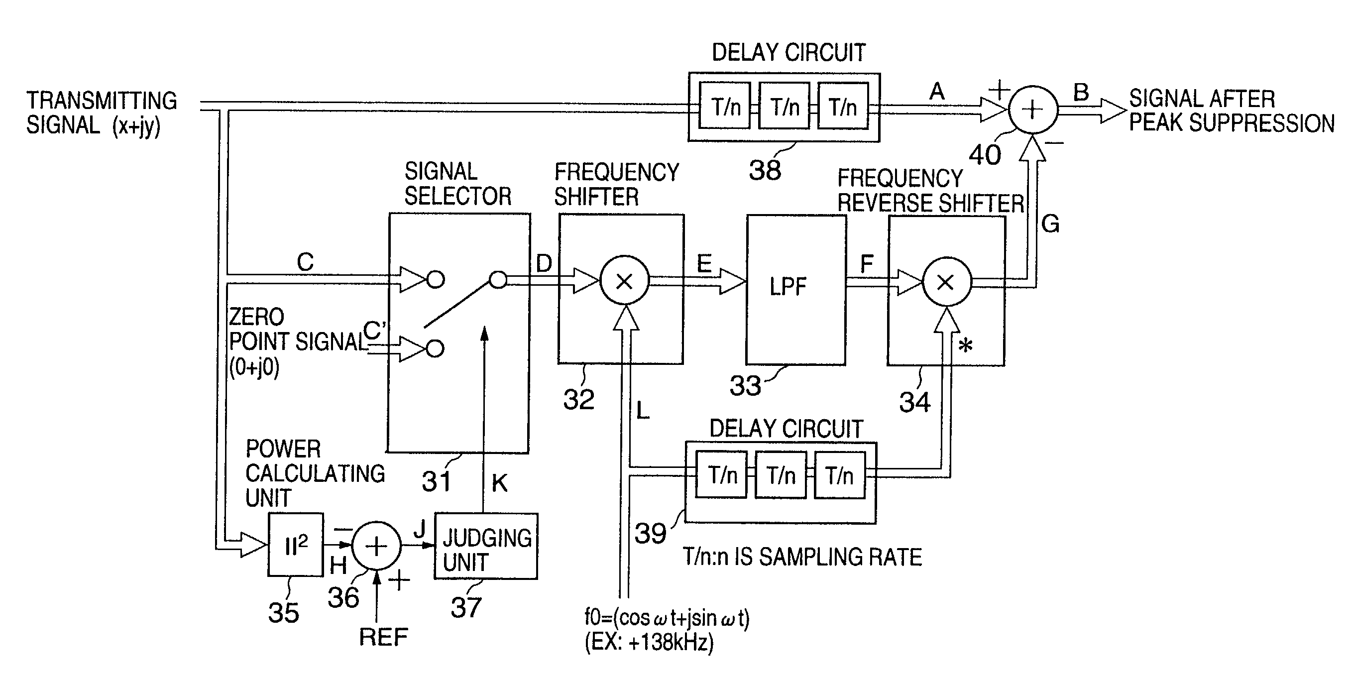
[0022]Still another object of the present invention is to provide a peak suppression method comprising the steps of (a) detecting a peak value exceeding a threshold value of a transmitting signal; (b) forming a peak value prediction signal which is limited to a noise cancelling frequency band of a receiving end, based on the detected peak value of the transmitting signal; and (c) subtracting the peak value prediction signal from the transmitting signal. According to the peak suppression method of the present invention, the peak suppression is carried out such that the peak value is not simply cut off, but is multiplexed as a noise component. Hence, at the receiving end, it is possible to restore the transmitting signal which has been subjected to the peak suppression in a noise cancelling stage. Therefore, it is possible to solve the saturation problem of the line driver and the like due to the peak of the transmitting signal in a multi-carrier transmission, to thereby improve the S / N ratio and to enable a high-speed data transmission.

Problems solved by technology

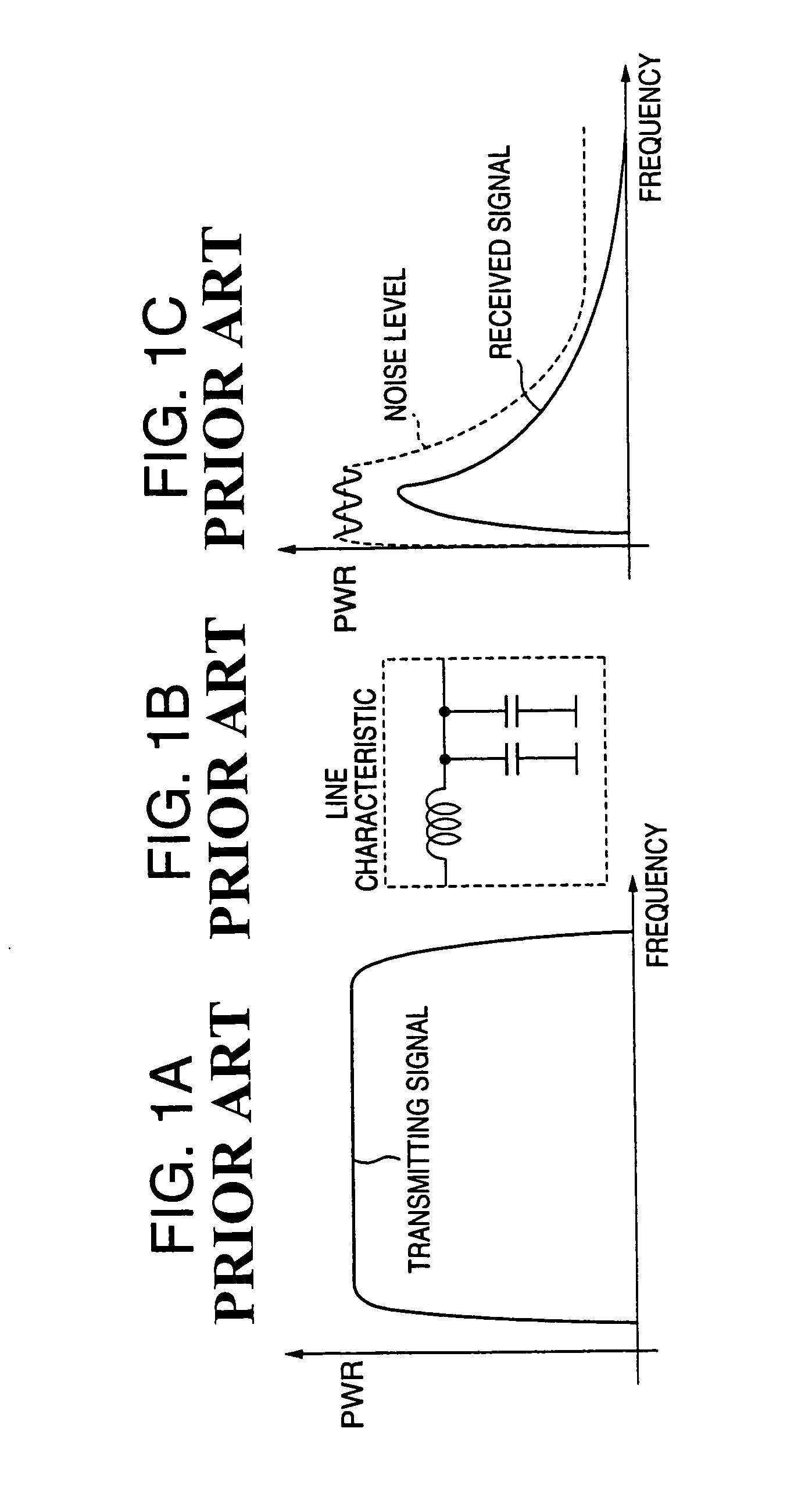
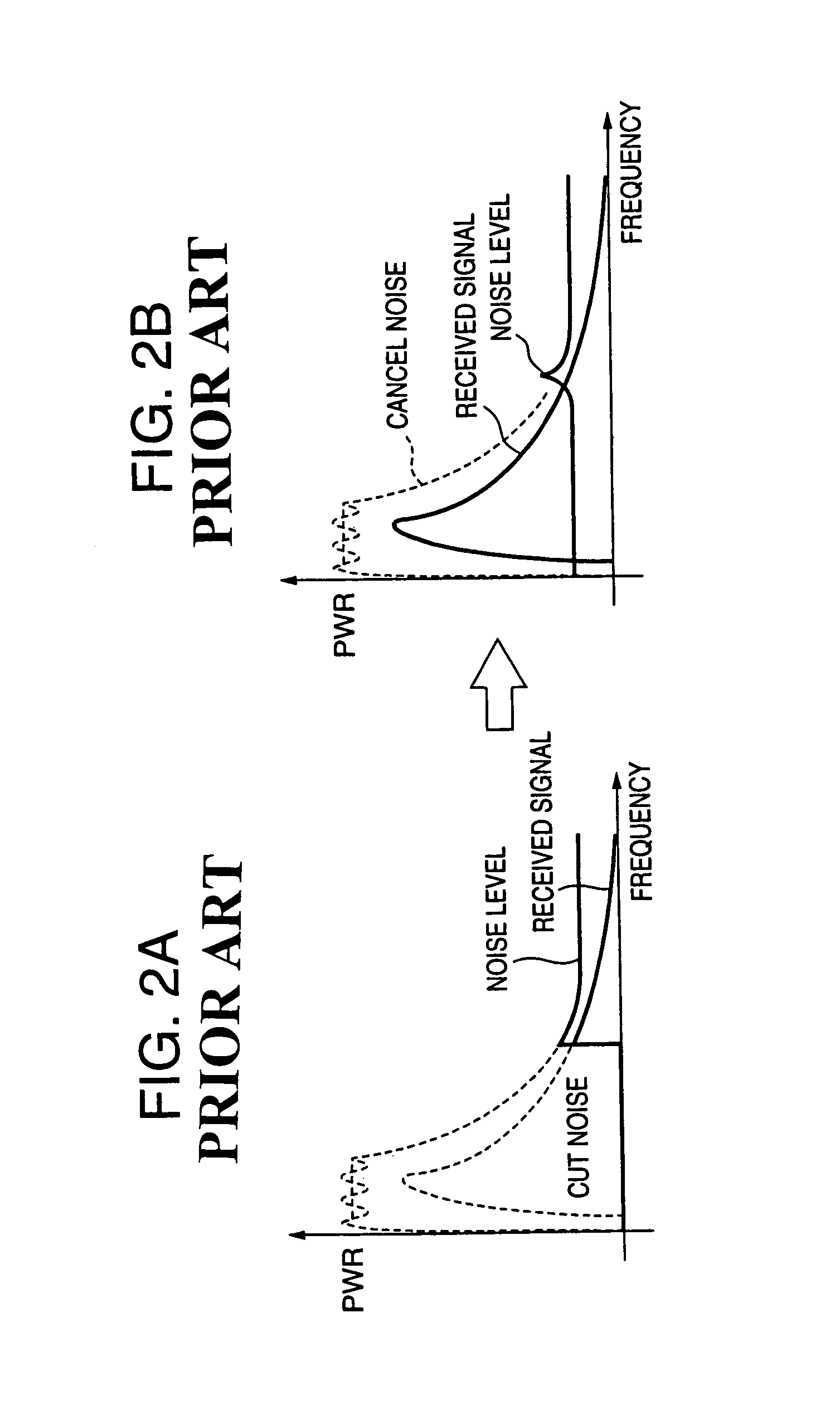
However, the S / N ratio is not improved by cutting the low frequency region where the received signal level is high.
When such a saturation occurs, the distortion of the received signal becomes large, to greatly deteriorate the S / N ratio.
But when the transmission level is reduced, no saturation occurs at the peak point, but the reception level is also reduced, thereby deteriorating the S / N ratio.
For this reason, even if the noise elimination is made based on the zero point insertion by the structure shown in FIG. 4, the S / N ratio assumes a negative value, and it may become impossible to make a high-speed data transmission.

Method used


Image

  • Peak suppression method and data transmission apparatus
  • Peak suppression method and data transmission apparatus
  • Peak suppression method and data transmission apparatus

Examples


Embodiment Construction

[0052]FIG. 6 is a system block diagram showing a first embodiment of a data transmission apparatus according to the present invention. This first embodiment of the data transmission apparatus employs a first embodiment of a peak suppression method according to the present invention. The data transmission apparatus shown in FIG. 6 includes a code converter 1, a signal generator 2, an inverse fast Fourier transform (IFFT) section 3 including a guard time (GT) adding function, a zero point inserting section 4, a peak suppressing section 21, a roll-off filter (ROF) 5, a modulator (MOD) 6, a digital-to-analog (D / A) converter 7, a lowpass filter (LPF) 8, and a transmission clock generator (TX-CLK) 9 which form a transmitting section. The code converter 1 includes the functions of a scrambler (SCR), a serial-to-parallel (S / P) converter, a Gray code / natural code (G / N) converter, a sum computing unit and the like. TX-line denotes a transmission line.

[0053]The data transmission apparatus also...


PUM


Abstract

A peak suppression method detects a peak value exceeding a threshold value of a transmitting signal, forms a peak value prediction signal which is limited to a noise cancelling frequency band of a receiving end, based on the detected peak value of the transmitting signal, and subtracts the peak value prediction signal from the transmitting signal.

Description

BACKGROUND OF THE INVENTION[0001]This application claims the benefit of a Japanese Patent Application No.2001-186273 filed Jun. 20, 2001, in the Japanese Patent Office, the disclosure of which is hereby incorporated by reference.[0002]1. Field of the Invention[0003]The present invention generally relates to peak suppression methods and data transmission apparatuses, and more particularly to a peak suppression method for suppressing a peak of a transmitting signal power in a system which transmits data by multi-carrier at a high speed so as not to deteriorate a signal-to-noise (S / N) ratio on a receiver end, and to a data transmission apparatus which transmits data by suppressing a peak of a transmitting signal.[0004]Multi-carrier data transmission which uses multi-carrier is applicable to various transmission systems including cable transmission such as ADSL and SDSL, wireless transmission such as OFDM, and optical transmission such as WDM.[0005]2. Description of the Related Art[0006...

Claims


Application Information

Patent Timeline
IPC IPC(8): H04L25/03H03C3/02H04J11/00H04B1/10H04B3/54H04J1/00H04L27/26
CPCH04L27/2624H04J1/00
Inventor KAKU, TAKASHIHIRAO, KYOKO
Owner FUJITSU LTD
Why Eureka
Try Eureka