
Exercise apparatus

Inactive Publication Date: 2005-12-27
CURTIS JAMES
View PDF9 Cites 28 Cited by
  • Summary
  • Abstract
  • Description
  • Claims
  • Application Information

AI Technical Summary

Benefits of technology

[0009]It is an object of the present invention to provide an exercise apparatus which is sized for convenient and attractive use in any room of a residence.
[0011]It is another object of the present invention to provide an exercise apparatus that is more easily and conveniently set-up or placed in position or condition for use.
[0012]It is another object of the present invention to provide an exercise apparatus that can be used without requiring the user to perform time-consuming, cumbersome, and awkward set-up procedures, or require the user to kneel, lift, or undertake other physically demanding tasks to prepare the exercise apparatus for use.
[0013]It is another object of the present invention to provide an exercise apparatus which allows the user to effectively exercise his or her upper and lower body simultaneously.
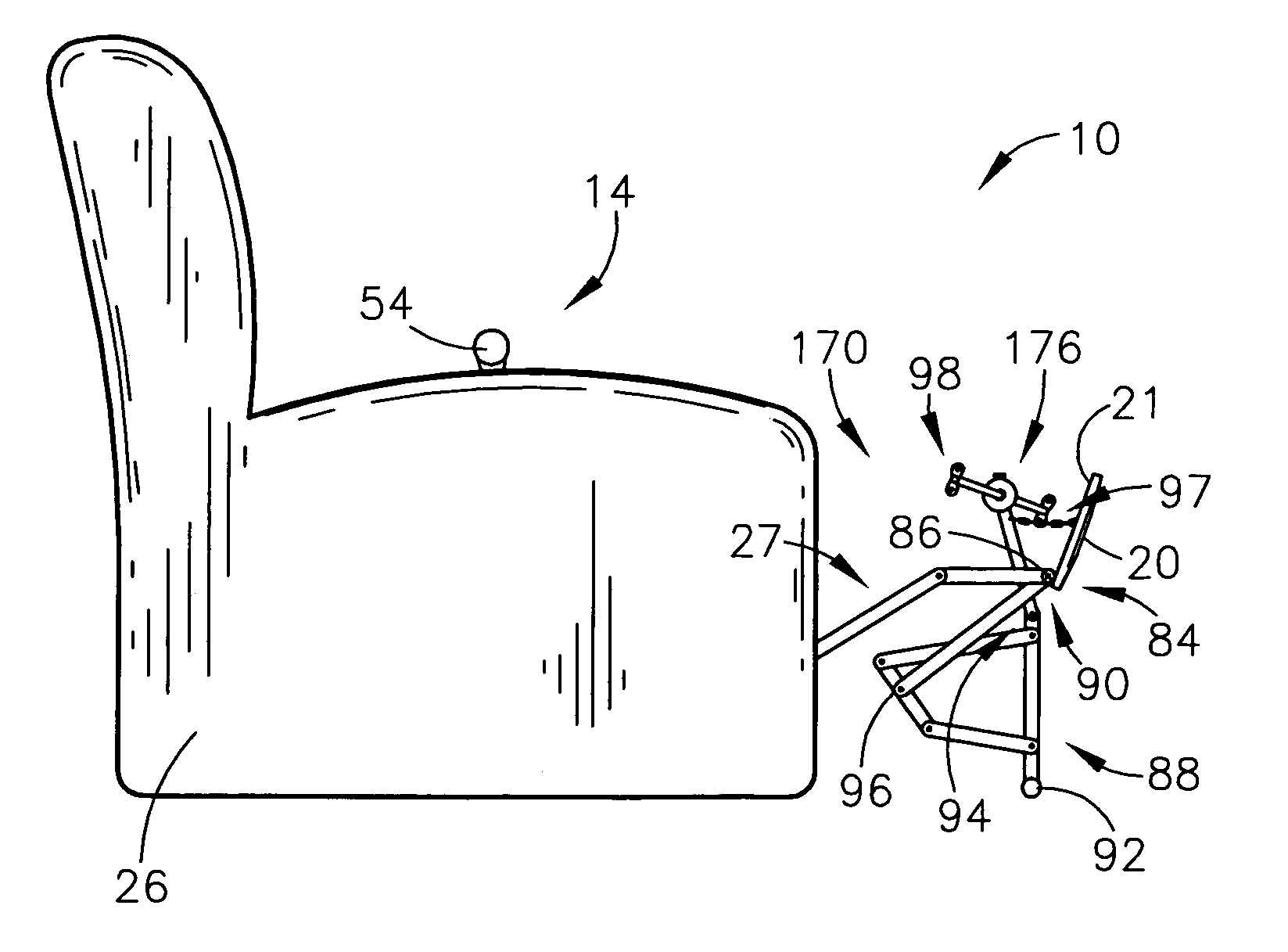
[0018]The pedal assembly is coupled with the underside of the footrest by a chain, wire, or other flexible connection such that pivoting the footrest forwardly exposes and automatically raises the pedal assembly for use. Thus, the present invention advantageously eliminates the awkward bending, stooping, or lifting required by prior art exerciser. The pedal assembly includes substantially conventional pedals configured for rotational movement. The pedal assembly is supported by the footrest support structure and the floor support. The pedal assembly may include a braking element, such as a rotational dampening mechanism, to create a resistence to the rotation of the pedal or pedals and increase the difficulty of the exercise.
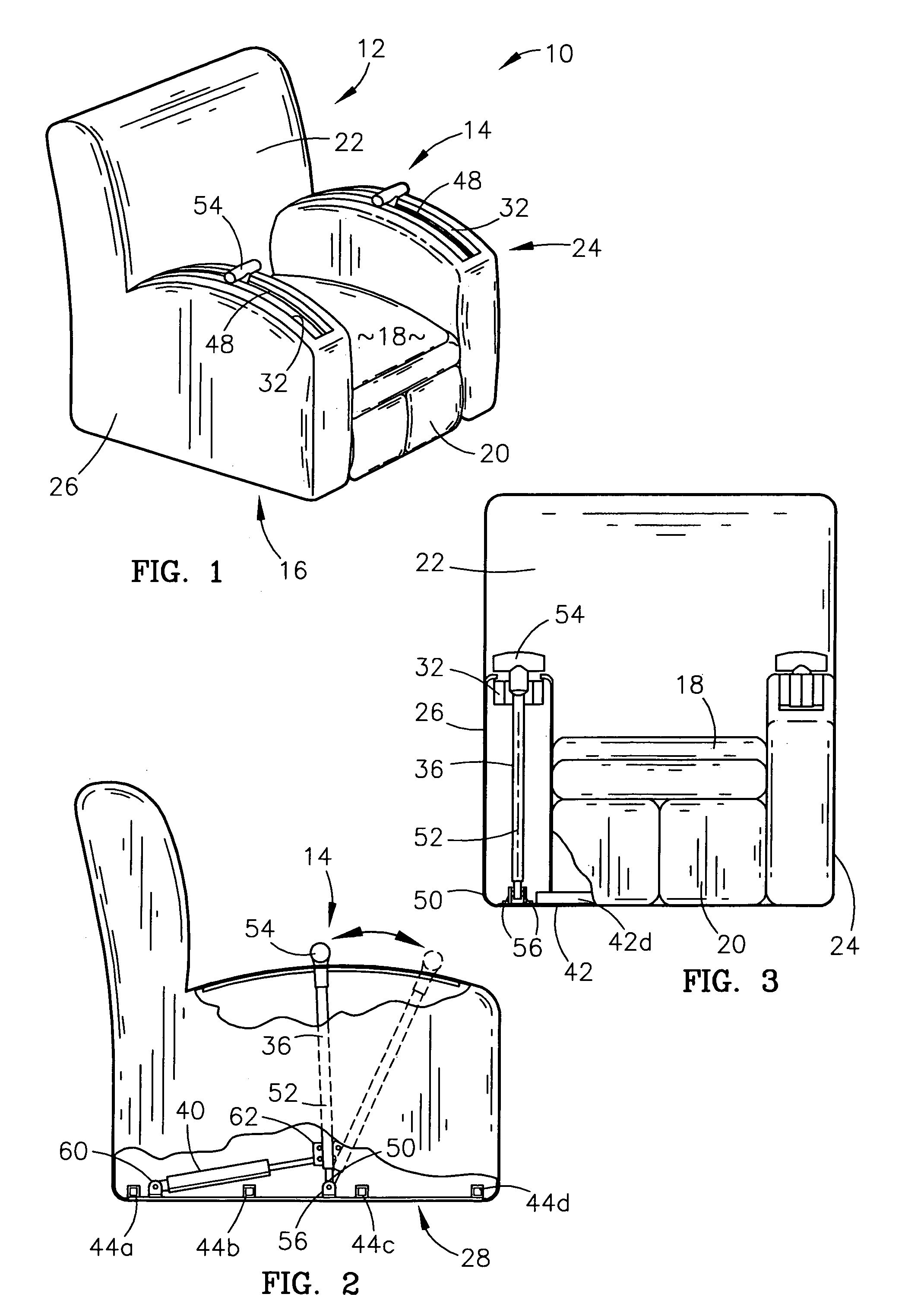
[0019]By providing an exercise apparatus with this construction, numerous advantages are obtained. For example, the combination of both a leg and arm exerciser in one piece of exercise equipment provides better fitness conditioning with reduced space requirements. Additionally, since the exercise apparatus doubles as a useful piece of furniture, it can be attractively placed in any area of a home. Accordingly, the exercise apparatus is more convenient and will be used more frequently. Additionally, the user can use the exercise apparatus without first rising from the chair and performing time-consuming, cumbersome, and awkward set-up procedures and without stooping or kneeling in an awkward or uncomfortable position. Once again, this increases the convenience and usage of the exercise apparatus. Finally, the construction of the arm-exerciser allows the user to adjust the resistance of the exercise movement “on-the-fly”. This also increases the convenience of the exercise apparatus.

Problems solved by technology

Most of these prior art exercise devices are large and bulky and thus require a significant amount of floor space.
Moreover, prior art equipment is typically manufactured with numerous moving parts formed of tubular steel or rubber and is therefore unsightly.
Since many users are too busy to travel to fitness centers, commercial exercise equipment is often underutilized.
Although these prior art devices are more convenient than large commercial devices, they suffer from many of the same limitations.
For example, prior art residential exercisers are unattractive and too large to be placed in living areas of the home.
Although exercise equipment of this type is more convenient than conventional exercise equipment, it presents several disadvantages of its own.
This operation is cumbersome and time-consuming and thus limits the convenience of the equipment, especially for senior users.
A second limitation of prior art furniture exercisers is that they provide limited exercise operations and do not allow the user to exercise his or her upper and lower body simultaneously.
A third limitation of prior art furniture exercisers, such as the apparatus disclosed in U.S. Pat. No. 5,470,298, is that they require the user to bend, stoop, lift, or otherwise awkwardly exert themselves in order to expose or access the normally concealed exercise mechanisms.
Many users, including the elderly or the disabled, may be incapable of the actions required to place the exerciser in position for use.

Method used


Image

  • Exercise apparatus
  • Exercise apparatus
  • Exercise apparatus

Examples


second embodiment

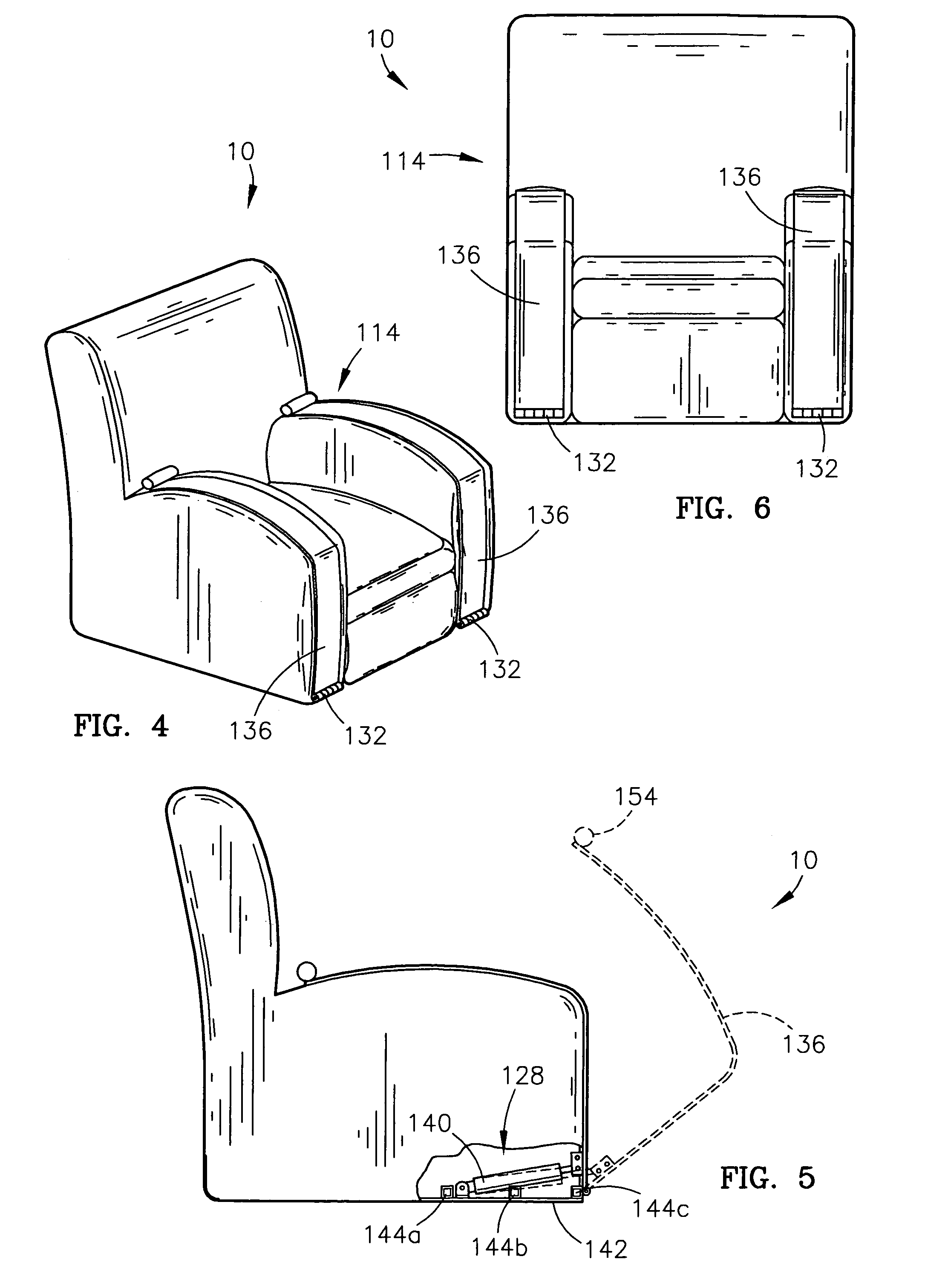
[0047]A preferred second embodiment of the arm-exercising station 114 is illustrated in FIGS. 4–6. In this embodiment, the arm exercising station 114 includes a support frame 128, a pair of elongated L-shaped left and right exercise bars 136, and a pair of left and right resistance devices 140.

[0048]In more detail, the support frame 128 is attached to the chair base portion 16 and includes a pair of elongated left and right side margins 142 and a plurality of tubular cross members 144a, 144b, and 144c. The side margins 142 are preferably formed of flattened ⅛ inch steel plates and are rigidly attached to the chair base portion 16 by conventional attachment devices. The tubular cross members 144a–c are preferably formed of hollow, square tubular steel having an exemplary width of one inch and are spaced apart and positioned intermediate the left and right side margins 142.

[0049]The left and right exercise bars 136 are positioned atop the chair armrest portions 24 and 26 and are subst...

first embodiment

[0051]As illustrated in FIGS. 7, 8 and 9, the exercise apparatus 10 may also include a preferred first embodiment of a leg-exercising station 70 mounted within the chair footrest. As illustrated in FIG. 7, the footrest includes walls defining an open rectangular cavity for mounting the components of the leg-exercising station 70. A pair of hinged lids are provided for enclosing the leg-exercising station 70 while the exercise apparatus is being used as a conventional recliner.

[0052]The leg exercising station 70 broadly includes an elongated outer support pole 72, an elongated inner support pole 74, and a pedal assembly 76. The outer support pole 72 is preferably formed of hollow tubular steel and extends perpendicularly through the footrest portion 20. The lower end of the outer support pole 72 is positioned to engage the floor surface when the footrest 20 is fully extended. The outer support pole 72 is supported within the footrest 20 by a plurality of L-shaped support braces 78.

[0...


PUM


Abstract

An exercise apparatus is provided which includes a chair, an arm-exercising station, and a leg-exercising station. The arm-exercising station is mounted in the armrests of the chair and includes a support frame attached to the base portion of the chair, a pair of elongated left and right exercise bars disposed within the left and right armrest portions of the chair operable for selective pivotal movement within the armrest portions, and a resistance device attached to the bars for resisting the pivotal movement of the bars. The leg-exercising station is associated with the underside of the footrest portion of the chair and includes a pedal assembly configured for rotational movement. The pedal assembly is automatically raised and positioned for use when the footrest is pivoted forwardly. The leg-exercising station is concealed within the chair when not in use.

Description

RELATED APPLICATIONS[0001]The present non-provisional patent application claims priority benefit, with regard to all common subject matter, of a copending U.S. provisional patent application titled FINAL EXERCISER, Ser. No. 60 / 405,804, filed Aug. 26, 2002. The identified provisional application is hereby incorporated by reference into the present application.BACKGROUND OF THE INVENTION[0002]1. Field of the Invention[0003]The present invention relates generally to exercise equipment and, more particularly, to an exercise apparatus which is incorporated in a piece of furniture such as a chair or recliner.[0004]2. Description of the Prior Art[0005]Due to increased public interest in fitness and health, a great variety of exercise equipment has been designed in recent years. Most such exercise equipment includes either a weight-resistance apparatus, a cycle apparatus, or both. Most of these prior art exercise devices are large and bulky and thus require a significant amount of floor spa...

Claims


Application Information

Patent Timeline
IPC IPC(8): A47C9/00A63B21/00A63B21/008A63B21/015A63B22/08A63B23/035A63B23/12
CPCA47C9/002A63B21/1492A63B22/0012A63B23/03575A63B23/12A63B21/008A63B21/015A63B2022/0041A63B2208/0233A63B2210/02A63B22/0605A63B2022/0652A63B21/4047A63B23/1209A63B23/03541A63B23/1263A63B21/4034A63B21/4035
Inventor CURTIS, JAMES
Owner CURTIS JAMES
Learn More