
Tilting mechanism for a chair and chair having the same

a tilting mechanism and chair technology, applied in the field of chairs, can solve the problems of difficult operation of the operating lever while a person sits in the seat, and difficulty in operating the operating lever, and achieve the effect of easy adjustmen

Active Publication Date: 2006-08-29
OKAMURA CORP
View PDF16 Cites 69 Cited by
  • Summary
  • Abstract
  • Description
  • Claims
  • Application Information

AI Technical Summary

Benefits of technology

[0005]In view of the foregoing disadvantages, it is an object of the invention to provide a chair in which a tilting angle of a backrest or a seat can be easily adjusted while a person sits in the seat without the positional relationship between the person and the operating lever being significantly changed even if the person is inclined together with the backrest of the chair.

Problems solved by technology

Especially when an armrest is provided, it is difficult to operate the operating lever since an arm of a person must be turned outward of the armrest.
However, it is hard to operate the operating levers while a person sits in the seat.
Thus, as the tilting angle becomes larger, the operating lever goes away from the shoulder of the person thereby making the operation harder.

Method used


Image

  • Tilting mechanism for a chair and chair having the same
  • Tilting mechanism for a chair and chair having the same
  • Tilting mechanism for a chair and chair having the same

Examples


Embodiment Construction

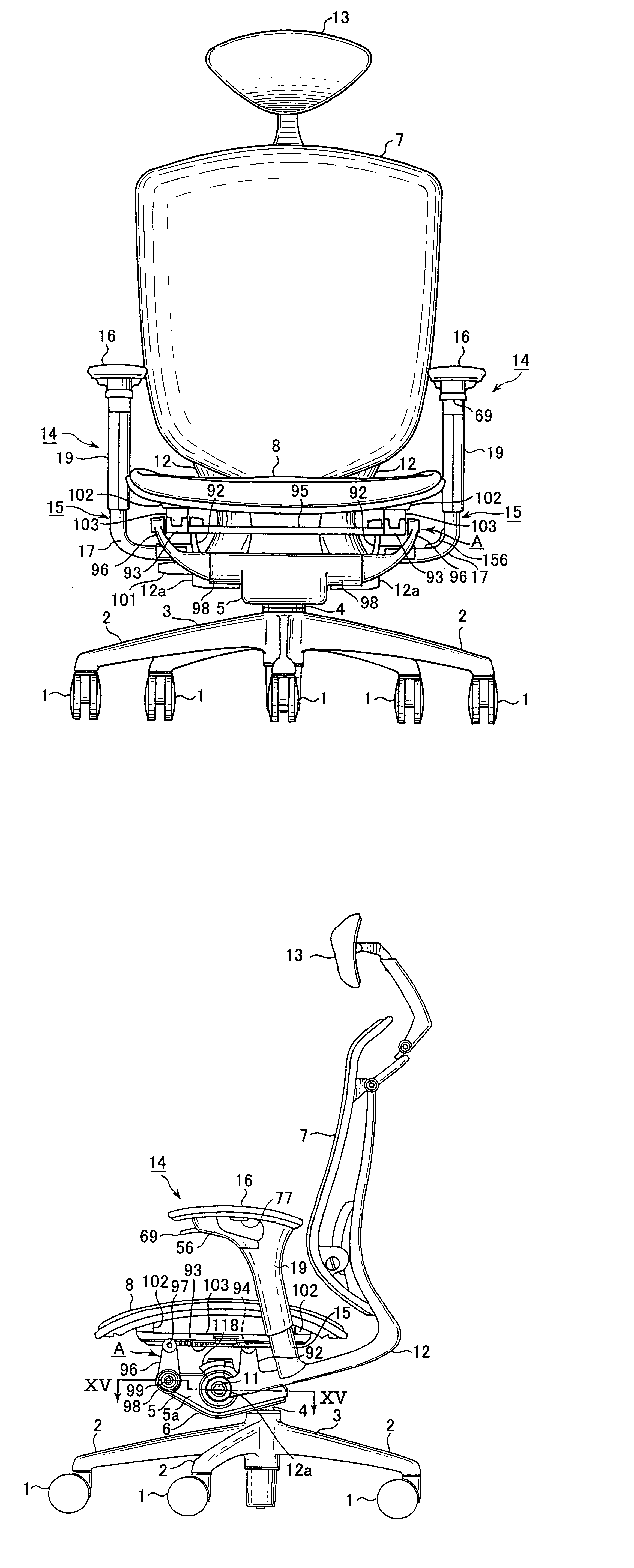
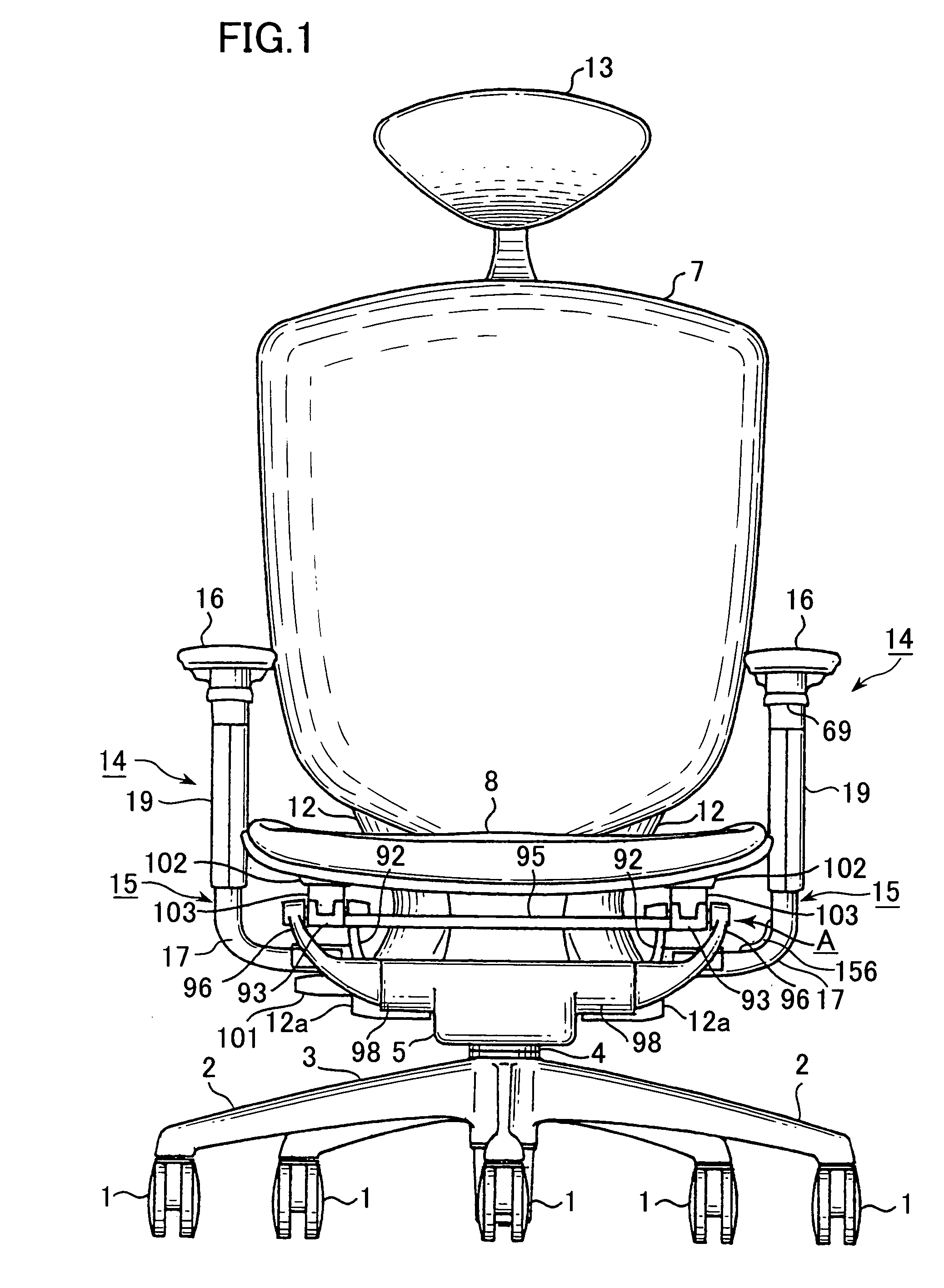
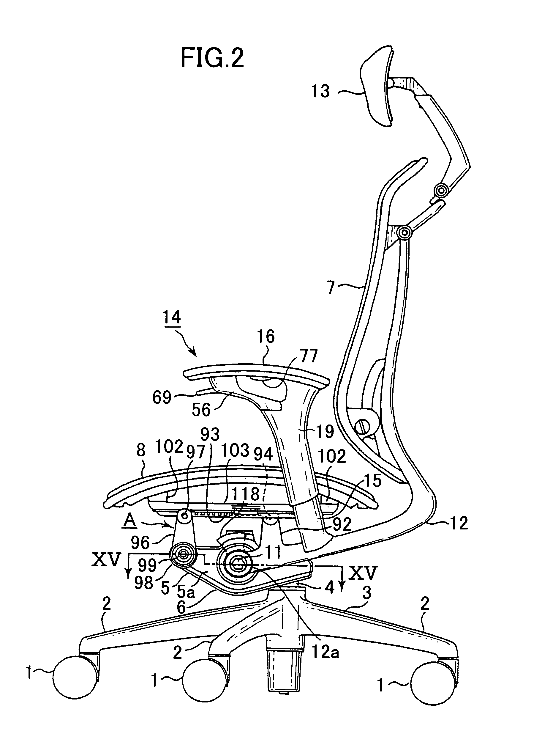
[0034]FIG. 1 is a front elevational view of a chair according to the present invention, and FIG. 2 is a side elevational view of the same. The chair has a leg 3 having five feet 2 radially. A telescopic column 4 which has a gas spring (not shown) stands on the center of the leg 3, and the rear end of a base 5 is fixed to the upper end of the column 4.

[0035]The base 4 opens at the bottom and is formed as a hollow box, and the bottom is covered with a detachable cover 6.

[0036]In the base 5, there are force promoting return means for returning a backrest 7 and a seat 8 in FIG. 13 and switching means for promoting force in FIG. 15, which will be described later.

[0037]In the middle of the base 5, a hexagonal shaft 11 penetrates in a transverse direction so as to turn on its axis.

[0038]The ends of the shaft 11 which projects from side walls 5a,5a of the base 5 are fixedly covered with tubular portions 12a,12a of a pair of L-sectioned backrest support rods 12,12 for supporting a backrest 7...


PUM


Abstract

A chair has a backrest and a pair of armrests. A pair of support struts for supporting the backrest is connected to a shaft of a base under a seat. The armrest is supported by an arm post. An operating lever is mounted on the upper front end of the arm post. When the backrest is tilted, it is held at a desired angle by pressing up the operating lever.

Description

BACKGROUND OF THE INVENTION[0001]The present invention relates to a chair which comprises an operating lever, a cable and a tilting device for locking a seat or a backrest at an optional tilting angle and releasing it.[0002]A conventional chair in which a backrest is locked at an optional stepwise angle usually has a tilting device in which a pin which projects on an operating lever rotatably mounted to a seat or an engagement lever related therewith is engaged with or disengaged from teeth formed on the outer circumferential surface of a sector gear which turns together with the backrest.[0003]However, in the chair, the operating lever is located on the rear side. Especially when an armrest is provided, it is difficult to operate the operating lever since an arm of a person must be turned outward of the armrest.[0004]In a home chair, under a seat, there are provided operating levers for adjusting a tilting angle of the backrest or the seat, height and promoting force. However, it i...

Claims


Application Information

Patent Timeline
IPC IPC(8): A47C1/024A47C1/022A47C1/03A47C7/54
CPCA47C1/03255A47C1/03A47C7/541A47C1/0305A47C1/0307A47C1/0308
Inventor IGARASHI, RYONUMA, NAOKINAKAYAMA, KENMASUNAGA, HIROSHI
Owner OKAMURA CORP
Learn More