
Rolling walker with arm rest platforms

a platform and rolling walker technology, applied in the field of rolling walker, can solve the problems of limited space for maneuvering the walker in a space limited environment, inability to fully support the user's weight, and the strength of the rolling walker or the “rollator” with the horizontal handle provides little support for users, so as to improve the ambulatory assistance, and improve the ambulatory support

Inactive Publication Date: 2005-07-21
BOHN DAVID L
View PDF25 Cites 71 Cited by
  • Summary
  • Abstract
  • Description
  • Claims
  • Application Information

AI Technical Summary

Benefits of technology

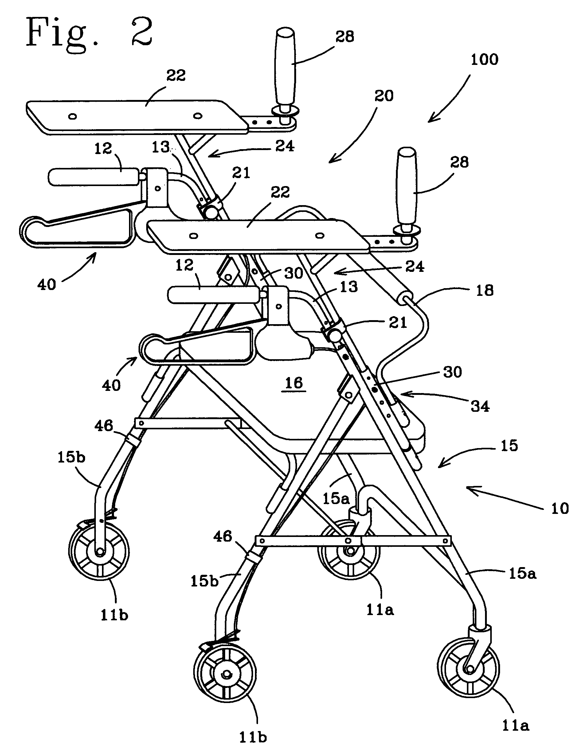
[0012] The above objectives are accomplished according to the present invention by providing a pair of arm rest platforms and vertical handles so the user of a rolling walker can have added or alternate support not provided by a conventional rolling walker or rollator. The arm rest platforms are supported at a vertical distance above the conventional walker by providing a pair of arm rest frames each extending between the main frame of the conventional walker and a respective arm rest platform. The arm rest frames each includes an main arm rest frame member carried by the main frame and an arm rest support member to carry the arm rest platform and vertical handles. The conventional hand brakes can also be relocated to be operated when gripping the vertical handles. The arm rest platforms can be adjusted in both horizontally and vertically with respect to the main frame of the conventional walker for better distribution of the user's weight.
[0013] In one embodiment of the invention, an improvement is provided in a conventional walker having four wheels, a main frame, a pair of horizontal handles each with a hand brake assembly operating two of the four wheels, a back rest member and a seat for a user to sit and rest when not walking. The improvement comprises a pair of arm rest frames each having a main arm rest frame member with an aperture near a bottom end. An arm rest support member is affixed at an upper end of each main arm rest frame member. A pair of arm rest support assemblies are each affixed to the main frame of the conventional walker to adjustably receive and support a respective arm rest frame so that the arm rest support members are essentially horizontally disposed at a vertical distance above the horizontal handles. An arm rest platform is adjustably attached to each arm rest platform support at a horizontal location to help support the user's weight. A pair of essentially vertically disposed handles are each affixed to a respective arm rest support member. The conventional walker also becomes a “platform walker” and the user can optionally stand more erect to distribute some additional weight on said arm rest platforms and grip said vertical handles to better steer the platform walker.
[0014] In another embodiment of the invention, an arm rest assembly in combination with a conventional four wheeled rolling walker provides improved ambulatory assistance to a user. The combination comprises a conventional walker having four wheels, a main frame, a pair of horizontal handles each with a hand brake assembly operating two of the four wheels and a seat with a back rest for providing basic ambulatory assistance to the user A pair of arm rest frames are provided with each rest frame having a main arm rest frame member with an aperture near a bottom end. An arm rest support member is affixed at an upper end of each main arm rest frame member. A pair of arm rest support assemblies of the main frame are provided to adjustably receive and support a respective arm rest frame so that the arm rest support members are essentially horizontally disposed at a vertical distance above the horizontal handles. An arm rest platform is adjustably attached to each arm rest support member at a horizontal location to help support the user's weight. A pair of essentially vertically disposed handles are each affixed to a respective arm rest support member. The arm rest platforms and the handles provide improved ambulatory assistance to the user.
[0015] In a further embodiment of the invention, a rolling walker provides ambulatory assistance to a user. The rolling walker comprises a main frame including main frame front legs and main frame rear legs supported on four wheels so that the main frame can be folded for storage and transporting from place to place. A seat with a back rest provides basic support for the user during periods of rest. A pair of arm rest frames are provided with each arm rest frame having a main arm rest frame member with an aperture near a lower end. An arm rest support member is affixed at an upper end of each main arm rest frame member. A pair of height adjustment assemblies of the main frame are provided to adjustably receive and support a respective arm rest frame so that the arm rest support members are essentially horizontally disposed at a vertical location above a ground surface. An arm rest platform is adjustably attached to each arm rest support member at a horizontal location to help support the user's weight. A pair of essentially vertically disposed handles are each affixed to a respective arm rest support member. The arm rest platforms and said handles provide improved ambulatory assistance to the user. A hand brake associated with each vertical handle is operated by the user to stop two of the four wheels from rotating.

Problems solved by technology

The conventional rolling walker or “rollator” with horizontal handles provides little support for users not strong enough to fully support their own weight.
The user is generally in a stooped position when gripping the horizontal handles, which is not very comfortable, and sometimes not possible for anyone having back problems.
The conventional walker is also positioned well ahead of the user; causing limited room for maneuvering the walker in a space limited environment, such as a bathroom or toilet area.

Method used


Image

  • Rolling walker with arm rest platforms
  • Rolling walker with arm rest platforms
  • Rolling walker with arm rest platforms

Examples


Embodiment Construction

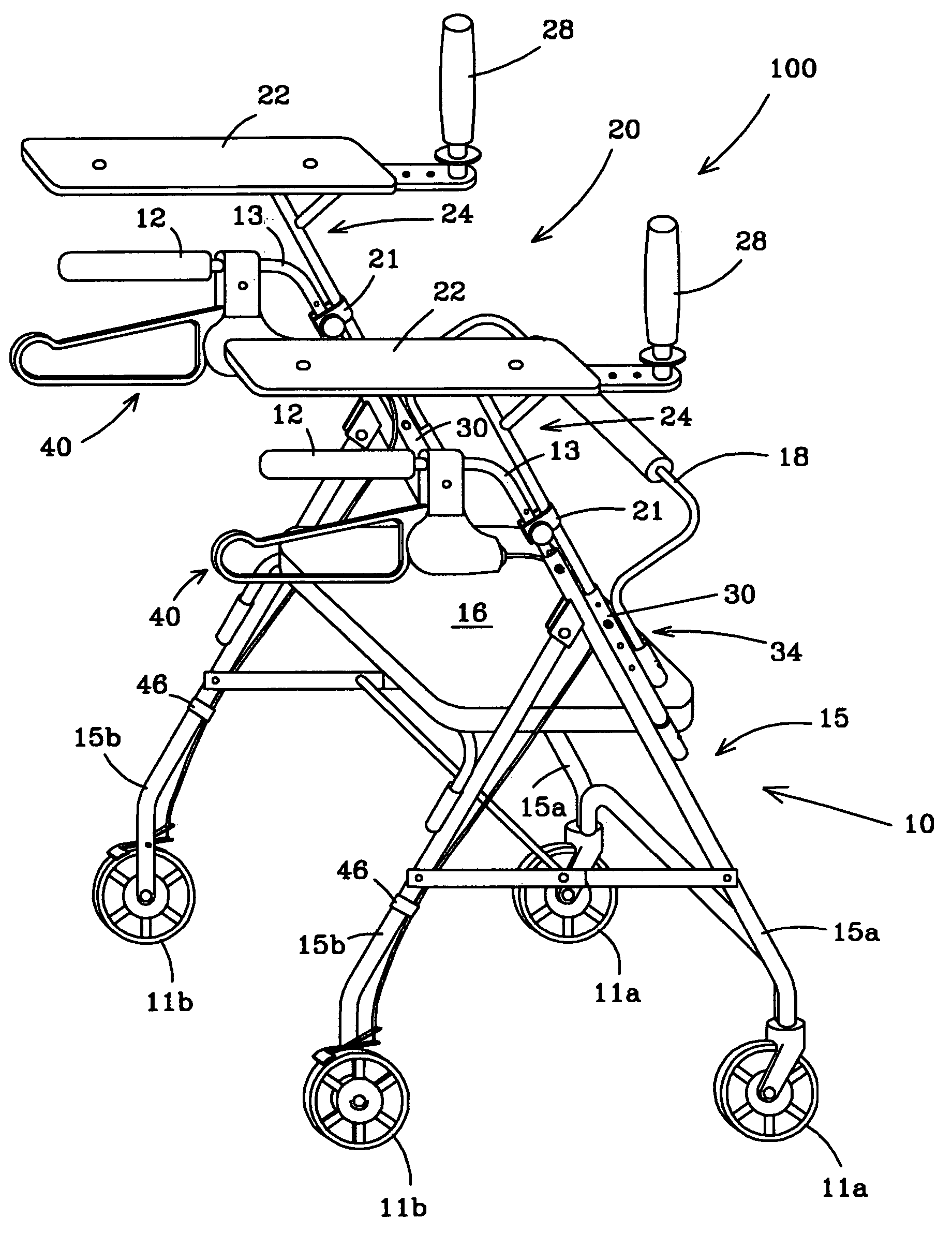
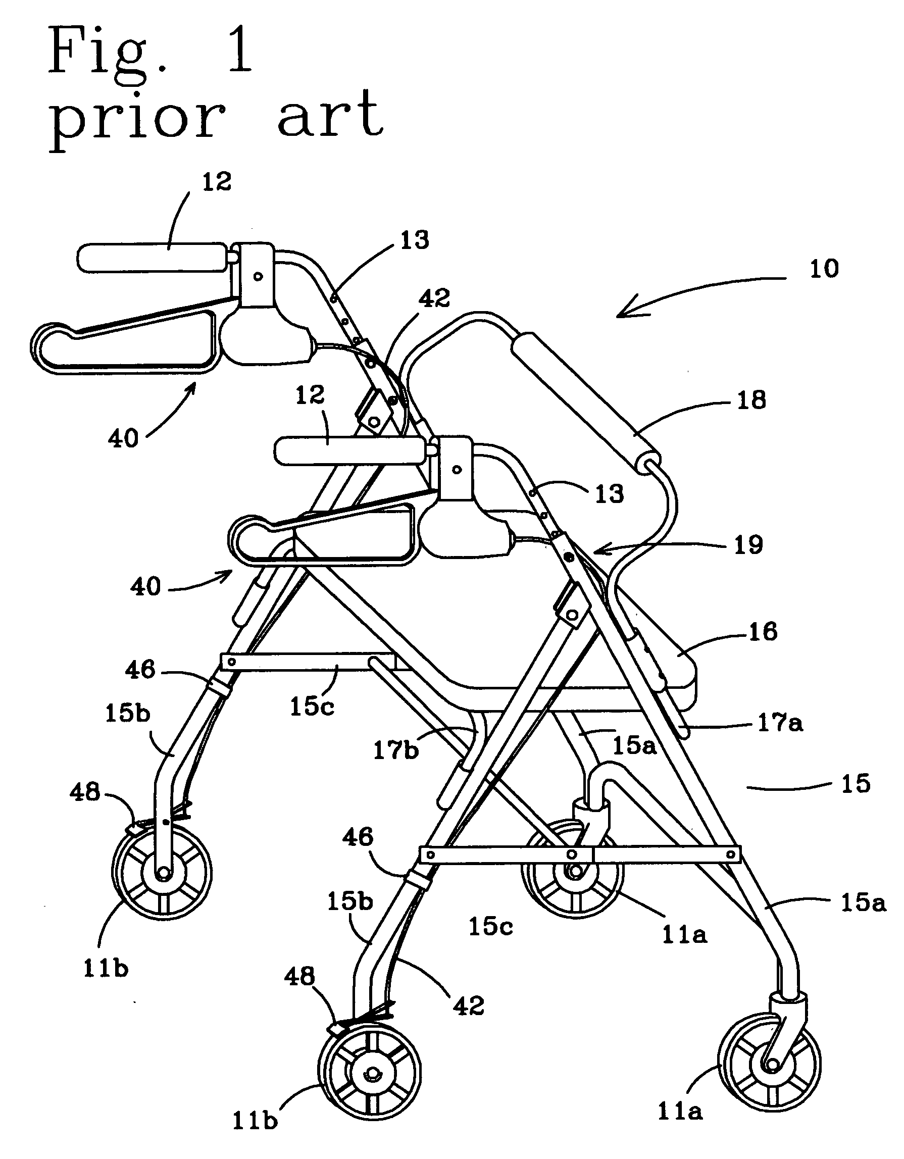
[0024] Referring now in more detail to the drawings, the invention will now be described in more detail. A conventional four wheeled rolling walker, known in the art as a “rollator” walker 10, is illustrated in FIG. 1. This conventional walker has been modified to include arm rest platforms 22 to provide a “platform walker”100, as illustrated in FIG. 2. The conventional walker includes a folding main frame 15, and a pair of horizontal handles 12 each supported by a handle frame 13 attached to the main frame with a main height adjustment device 19. The main frame includes a pair of main frame front legs 15a, a pair of main frame rear legs 15b and a rear leg pivot device 14 so that the main frame folds for storage and transporting from place to place. A pair of main frame braces 15c maintains the conventional walker in a deployed configuration. Two rear wheels of the four wheels operate as breaking wheels 11b and two front wheels operate as castered wheels 11a. A hand brake 40 adjacen...


PUM


Abstract

The present invention provides a pair of arm rest platforms and vertical handles so the user of a rolling walker can have added or alternate support not provided by a conventional rolling walker or rollator. The arm rest platforms are supported at a vertical distance above the conventional walker by providing a pair of arm rest frames each extending between the main frame of the conventional walker and a respective arm rest platform. The arm rest frames each includes an main arm rest frame member carried by the main frame of the conventional walker and an arm rest support member to carry the arm rest platform and vertical handles. The conventional hand brakes can also be relocated; to be operated when gripping the vertical handles. The arm rest platforms can be adjusted in both horizontally and vertically with respect to the main frame of the conventional walker for better distribution of the user's weight.

Description

BACKGROUND OF THE INVENTION [0001] This invention is directed to walkers to assist medical patients in walking and more particularly to a 4-wheeled rolling walker having horizontal handles with hand brakes made for strolling outdoors, and having a seat for periodic periods of rest or for transporting the patient when seated. [0002] There are a number of conventional walkers that combine a light weight folding frame that is easy to lift and store and perfect for strolling outdoors. They include four wheels of relatively small size (i.e. six inch diameter) with two wheels having a hand brake assembly. A seat with a backrest is provided so the user can set the handbrake and take a rest. A basket may also be provided under the seat for shopping and / or to carry personal items as the user grips the horizontal handles that assist them in walking. The user controls the movement of the walker by gripping the horizontal handles and steering the conventional walker by pushing or pulling one ha...

Claims


Application Information

Patent Timeline
IPC IPC(8): A61H3/00A61H3/04B62M1/00
CPCA61H3/04A61H2201/1633A61H2003/046A61H2003/006
Inventor BOHN, DAVID L.
Owner BOHN DAVID L
Learn More