
Absorption chiller-heater

Inactive Publication Date: 2005-12-27
YAZAKI ENERGY SYST
View PDF8 Cites 23 Cited by
  • Summary
  • Abstract
  • Description
  • Claims
  • Application Information

AI Technical Summary

Benefits of technology

[0014]When such a constitution is constructed, in the case in which the absorption chiller-heater is not operated when the external machine generating the exhaust gas generates the exhaust gas, exhaust gas at the introducing flow path can be cut off from flowing by the damper provided to the flow path switching device to thereby bring about a state of making the exhaust gas flow to the bypass flow path. At this occasion, the exhaust gas is cut off from flowing in the exhaust flow path by the damper and the gas delivering device is driven, however, the gas delivering device may only be able to increase a pressure of a closed space including a flow path of the exhaust gas at inside of the exhaust gas fired regenerator between the damper for cutting off the exhaust gas from flowing in the introducing flow path and the damper for cutting off the exhaust gas from flowing in the exhaust flow path and therefore, a gas amount of the blower can be restrained. Further, a number of the dampers can be made to be smaller than that of the related art and the constitution can be simplified. That is, the gas volume of the blower can be restrained while simplifying the constitution.
[0015]Further, when there is constructed a constitution in which the flow path switching device includes a first damper provided at the introducing flow path and a second damper provided at the bypass flow path, a degree of freedom of a position of installing the damper is increased.
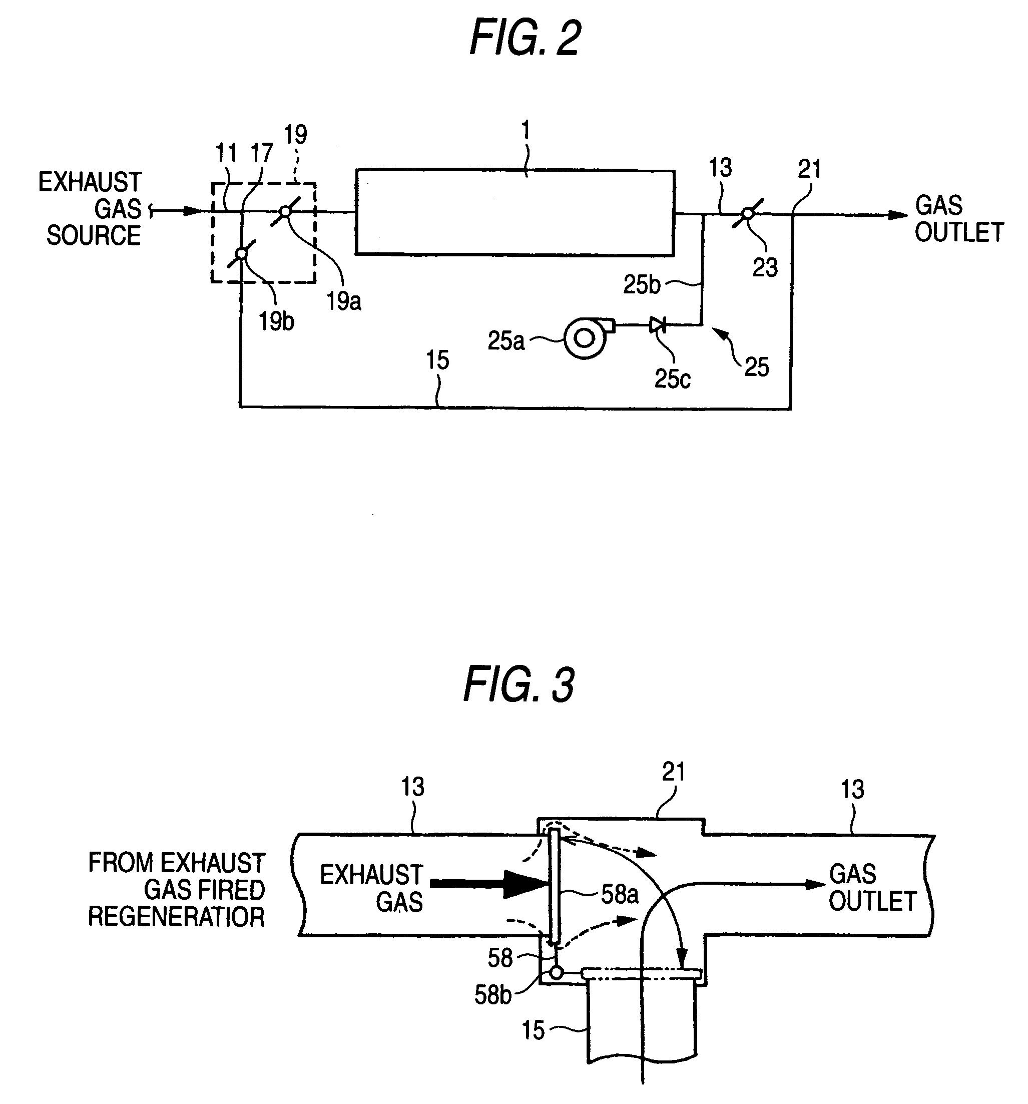
[0017]In contrast thereto, when there is constructed a constitution in which the flow path switching device is a three-way damper provided at a merged portion of the introducing flow path and the bypass flow path, flow of the exhaust gas pushes the movable plate of the damper in a closing direction and therefore, leakage is not increased and the three-way damper can be used. Therefore, the number of dampers is further reduced and the constitution can further be simplified.

Problems solved by technology

However, there is a limit in sealing performance of the damper in view of the structure, flow of the exhaust gas cannot completely be stopped and leakage of the exhaust gas is brought about.
Therefore, by heat of the exhaust gas flowing to the exhaust gas fired regenerator by leakage of the damper, invariably, corrosion or the like is brought about at a member constituting the exhaust gas fired regenerator due to crystallization of the absorbing solution at inside of the exhaust gas fired regenerator, occurrence of dew condensation at inside of the flow path of the exhaust gas at inside of the exhaust gas fired regenerator and the like.
However, the larger the gas volume of the blower, the more increased is power consumption, noise or the like and it is necessary to restrain the gas volume of the blower as less as possible.
However, the constitution is complicated such that the number of the dampers is increased or the like.

Method used


Image

  • Absorption chiller-heater
  • Absorption chiller-heater
  • Absorption chiller-heater

Examples


Embodiment Construction

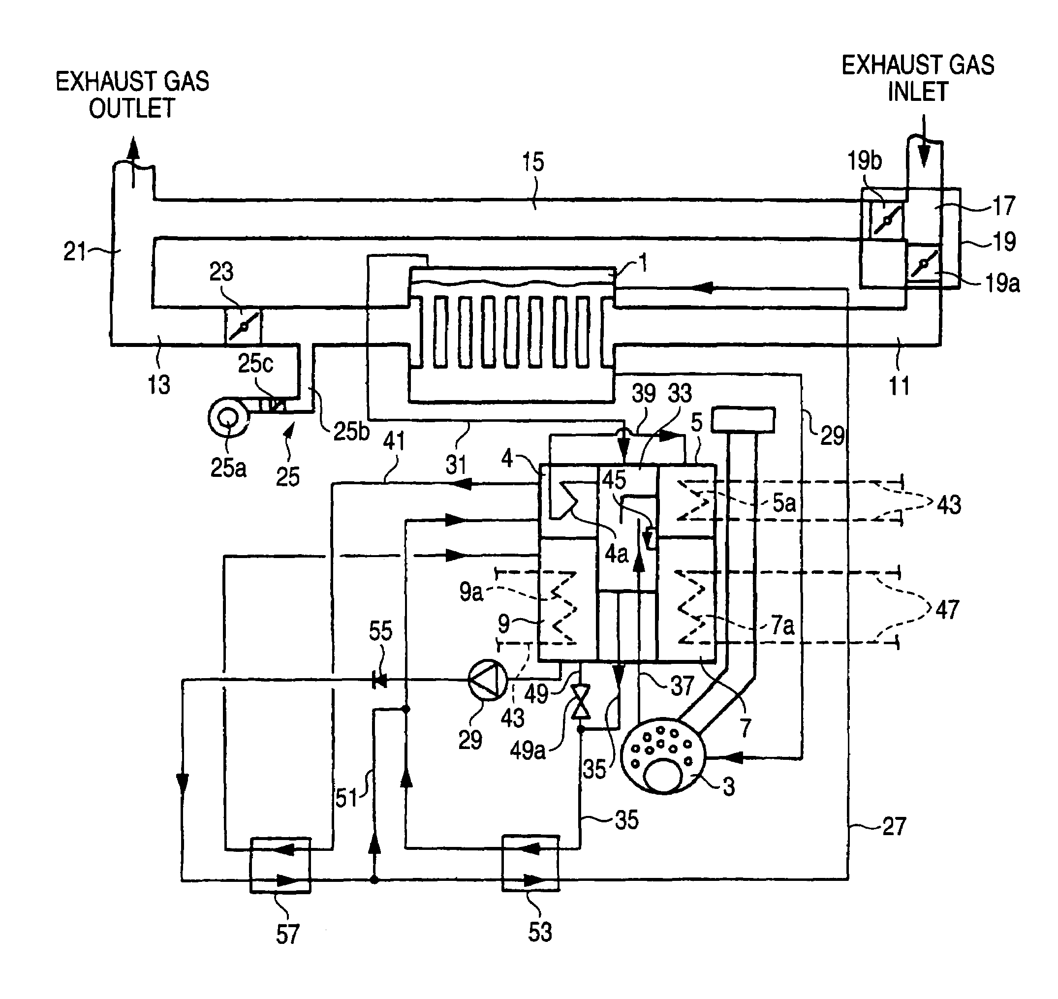
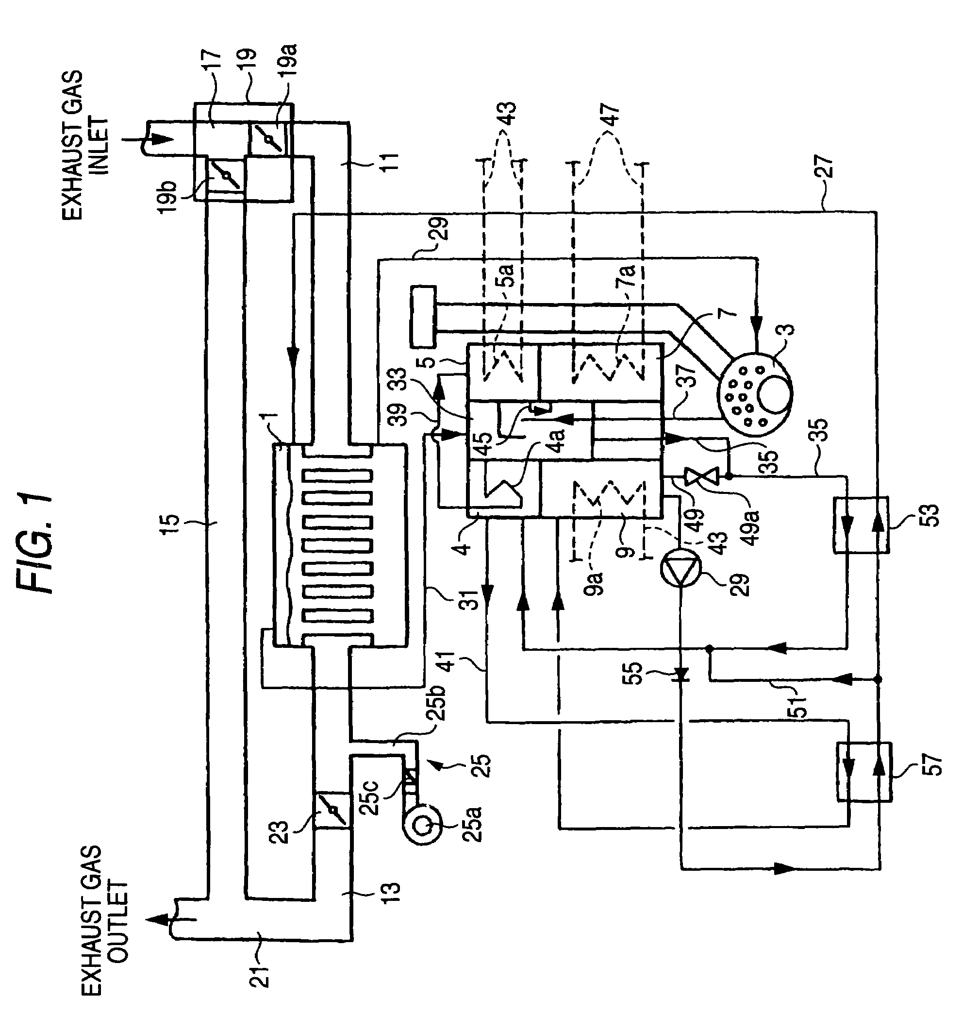
[0023]An explanation will be given of an embodiment of an absorption chiller-heater constituted by applying the invention in reference to FIG. 1 and FIG. 2 as follows. FIG. 1 is a diagram showing an outline constitution of an absorption chiller-heater constituted by applying the invention. FIG. 2 is a diagram showing an outline constitution of an exhaust flow path connected to an exhaust gas fired regenerator of the absorption chiller-heater constituted by applying the invention.

[0024]As shown by FIG. 1, the absorption chiller-heater of the embodiment is constituted by an exhaust gas fired regenerator 1, a directly fired regenerator 3, a low temperature regenerator 4, a condenser 5, an evaporator 7, an absorber 9 and the like. The exhaust gas fired regenerator 1 is for carrying out heat exchange between exhaust gas from external machine generating exhaust gas by combustion and a diluted solution and generating a cooling medium vapor and a concentrated solution by heating the diluted...


PUM


Abstract

There is constructed a constitution including an exhaust gas fired regenerator constituting a heat source by exhaust gas from an external machine generating the exhaust gas, an introducing flow path for guiding the exhaust gas to the exhaust gas fired regenerator, an exhaust flow path for exhausting the exhaust gas from the exhaust gas fired regenerator, a bypass flow path branched from the introducing flow path, flow path switching device including a first damper provided at the introducing flow path and a second damper provided at the bypass flow path for switching flow of the exhaust gas to the introducing flow path and the bypass flow path, a damper provided at the exhaust flow path for cutting off the exhaust gas from flowing in the exhaust flow path and gas delivering device for blowing a gas to a portion of the exhaust flow path between the damper for cutting off the exhaust gas from flowing and the exhaust gas fired regenerator.

Description

[0001]The present application is based on Japanese Patent Application No. 2003-31007, the entire contents of which are incorporated herein by reference.BACKGROUND OF THE INVENTION[0002]1. Field of the Invention[0003]The present invention relates to an absorption chiller-heater, particularly relates to an absorption chiller-heater having an exhaust gas fired regenerator constituting a heat source by exhaust gas.[0004]2. Related Art[0005]According to an absorption chiller-heater having an exhaust gas fired regenerator constituting a heat source by exhaust gas, exhaust gas from an external machine generating the exhaust gas is guided to the exhaust gas fired regenerator via an introducing flow path and the exhaust gas is exhausted from the exhaust gas fired regenerator by an exhaust flow path. At this occasion, in the case in which the absorption chiller-heater is not operated while the external machine generates the exhaust gas, by heat input from the exhaust gas or the like, corrosio...

Claims


Application Information

Patent Timeline
IPC IPC(8): F25B27/02F25B15/00F25B33/00
CPCF25B27/02F25B33/00F25B2333/003Y02A30/274
Inventor YAMAZAKI, TAKAYUKI
Owner YAZAKI ENERGY SYST
Learn More