
Parallel detection chromatography systems

a liquid chromatography and parallel separation technology, applied in the direction of sampling, instruments, measurement devices, etc., can solve the problems of complex and time-consuming assembly, inability to perform multiple parallel separations, and interface with other system components through threaded fittings

Inactive Publication Date: 2005-12-20
AGILENT TECH INC
View PDF75 Cites 61 Cited by
  • Summary
  • Abstract
  • Description
  • Claims
  • Application Information

AI Technical Summary

Benefits of technology

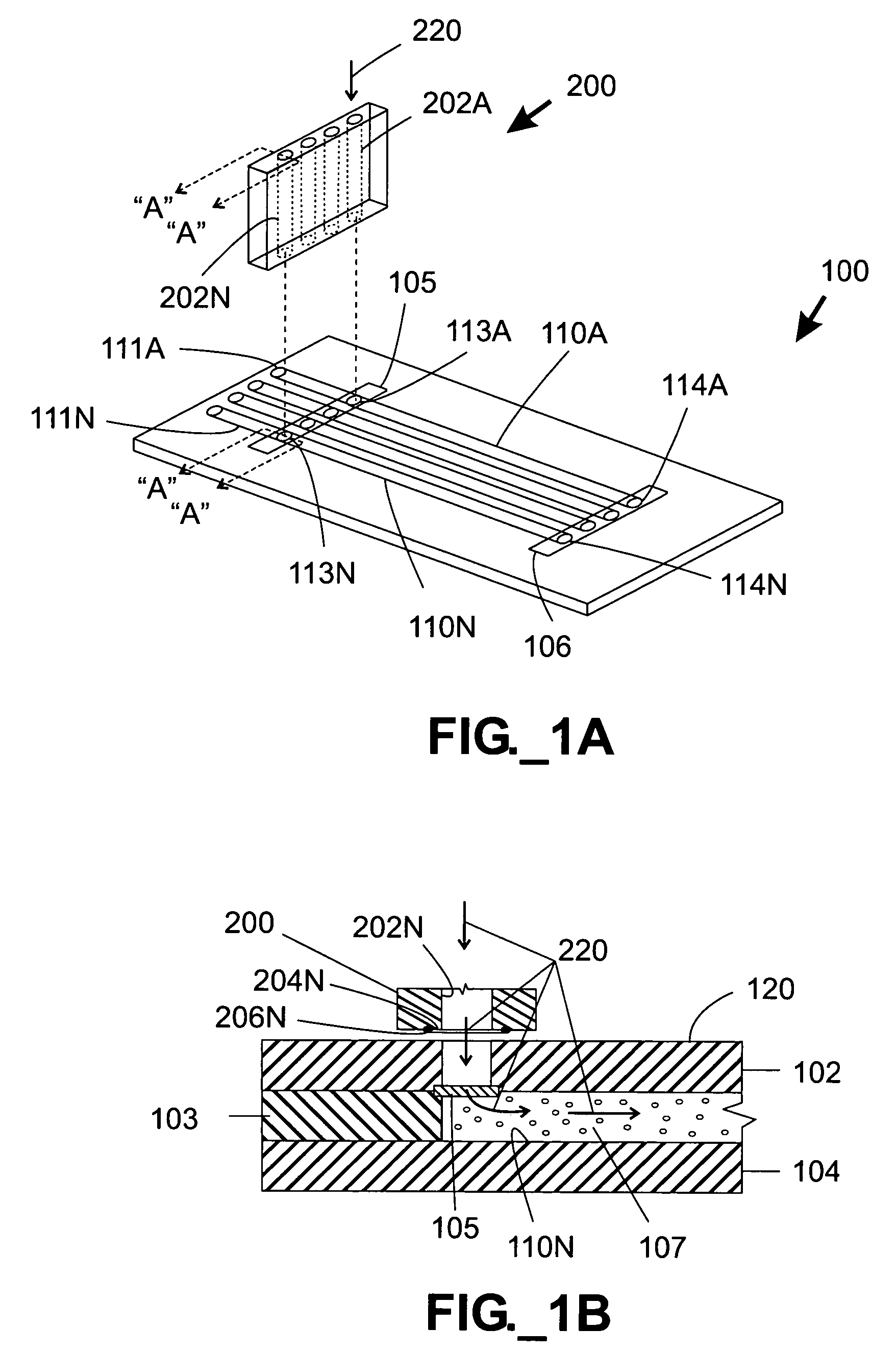
The present invention relates to high throughput liquid chromatography systems with multiple separation columns. The technical effects of this invention include simplifying the assembly and operation of chromatography systems, allowing for easy installation and operation of multiple separation columns within a single system, and providing sufficient detection capability for flow-through analyses. Additionally, the invention provides microfluidic interfaces capable of maintaining fluid-tight seals at the high operating pressures typically associated with high performance liquid chromatography.

Problems solved by technology

Nonetheless, the ability to perform multiple parallel separations has been limited for a variety of reasons.
One drawback of this type of separation column is that its assembly is complex and time-consuming.
Another drawback of conventional tube-based separation columns is they interface with other system components through threaded fittings, which are not amenable to automated engagement and disengagement due to the difficulty of manipulating such fittings along with strict alignment tolerances.
As a result, conventional multi-column LC systems offer little benefit in terms of simplicity or volumetric savings with the addition of each incremental separation column.
Another difficulty with integrating a large number of separation columns into a single system includes providing sufficient detection capability.
High-sensitivity detectors such as photomultiplier tubes are typically both expensive and bulky, thus limiting the scalability of multi-column LC systems and rendering it difficult for them to include large numbers of separation columns.
Thus, while microscale systems would appear to offer advantages in terms of packaging multiple columns into a limited volume, such systems may suffer from limited sensitivity.

Method used


Image

  • Parallel detection chromatography systems
  • Parallel detection chromatography systems
  • Parallel detection chromatography systems

Examples


Embodiment Construction

Definitions

[0043]The terms “column” or “separation column” as used herein are used interchangeably and refer to a region of a fluidic device that contains stationary phase material and is adapted to perform a separation process.

[0044]The term “fluidic distribution network” refers to an interconnected, branched group of channels and / or conduits capable of adapted to divide a fluid stream into multiple substreams.

[0045]The term “frit” refers to a liquid-permeable material adapted to retain stationary phase material within a separation column.

[0046]The term “interpenetrably bound” as used herein refers to the condition of two adjacent polymer surfaces being bound along a substantially indistinct interface resulting from diffusion of polymer chains from each surface into the other.

[0047]The term “microfluidic” as used herein refers to structures or devices through which one or more fluids are capable of being passed or directed and having at least one dimension less than about 500 micro...


PUM

PropertyMeasurementUnit
lengthaaaaaaaaaa
temperatureaaaaaaaaaa
pressureaaaaaaaaaa

Abstract

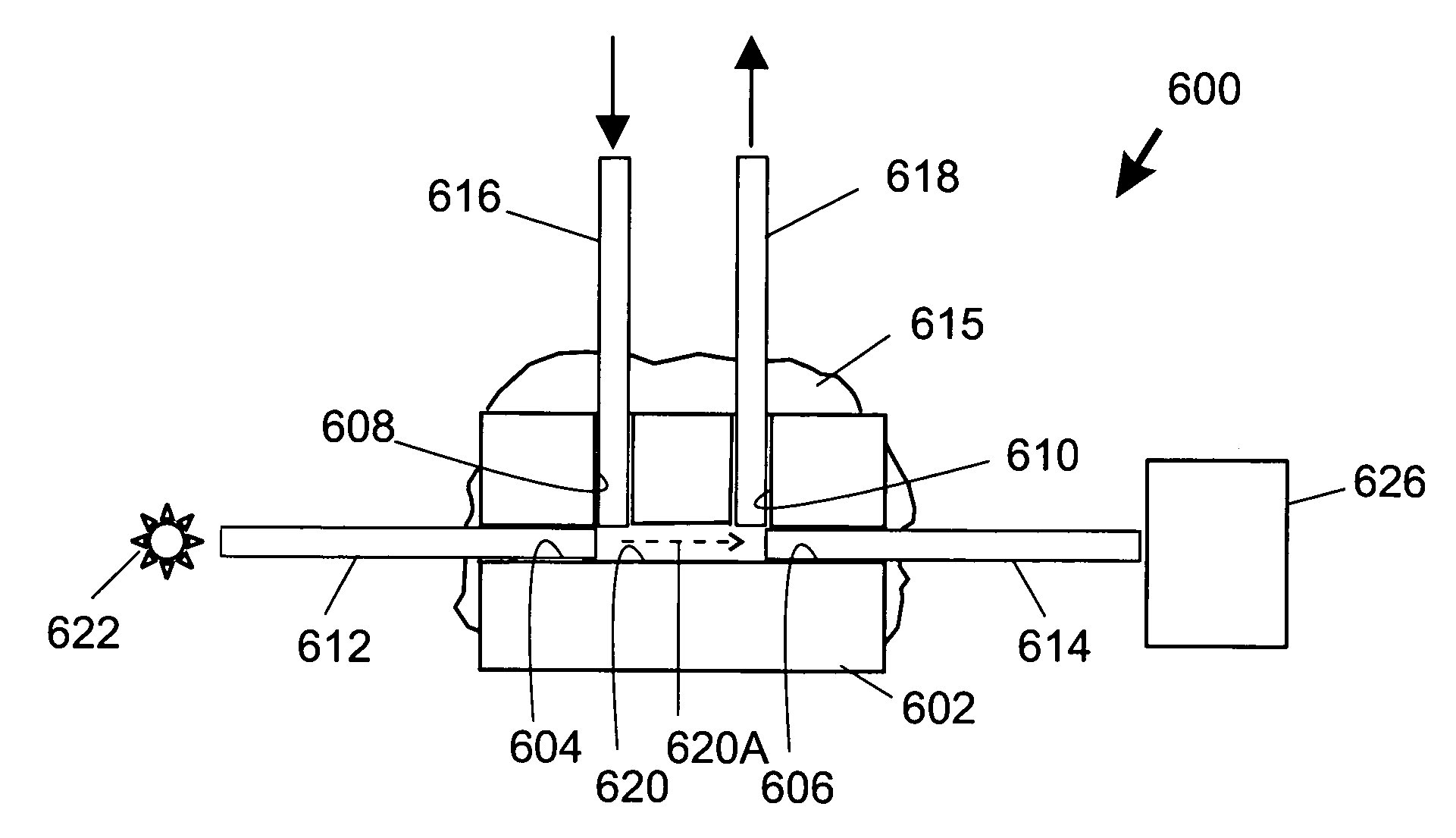
High throughput liquid chromatography systems include multiple separation columns and multiple flow-through detection regions in sensory communication with a common radiation source and a multi-channel detector. Preferred detector types include a multi-anode photomultiplier tube, a charge-coupled device detector, a diode array, and a photodiode array. In certain embodiments, separation columns are microfluidic and integrated into a unitary microfluidic device. The optical path through a detection region is preferably coaxial with the path of eluate flow along a flow axis through a detection region. On-board or off-board detection regions may be provided.

Description

STATEMENT OF RELATED APPLICATION(S)[0001]This application claims benefit of commonly assigned U.S. provisional patent application Ser. No. 60 / 422,901 filed Oct. 31, 2002.FIELD OF THE INVENTION[0002]The present invention relates to high throughput liquid chromatography systems having multiple separation columns.BACKGROUND OF THE INVENTION[0003]Recent developments in the pharmaceutical industry and in combinatorial chemistry have exponentially increased the number of potentially useful chemical compounds. It is desirable to characterize these compounds to identify their active components and / or establish processes for their synthesis.[0004]One useful analytical process is chromatography, which encompasses a number of methods that are used for separating ions or molecules that are dissolved in or otherwise mixed into a solvent. Liquid chromatography (“LC”) is a physical method of separation wherein a liquid “mobile phase” (typically consisting of one or more solvents) carries a sample ...

Claims


Application Information

Patent Timeline
Patent Type & Authority Patents(United States)
IPC IPC(8): G01N30/46G01N30/60G01N30/74G01N30/88
CPCG01N30/466G01N30/6091G01N30/6095G01N30/74G01N30/6026G01N30/6047G01N2030/746G01N2030/8881
Inventor HOBBS, STEVEN E.DUONG, HAU H.
Owner AGILENT TECH INC
Learn More