
Obstruction avoidance continuous seam welding system

a continuous seam welding and obstruction avoidance technology, applied in the field of roof membrane seam welders, can solve the problems of complex welding process, deficient disclosed seaming device, and difficulty in obtaining uniform and continuous seam/weld between the adjoining membranes, and achieves uniform pressure, low speed, and optimal heat gradient

Inactive Publication Date: 2005-12-13
FIRESTONE BUILDING PRODS
View PDF43 Cites 16 Cited by
  • Summary
  • Abstract
  • Description
  • Claims
  • Application Information

AI Technical Summary

Benefits of technology

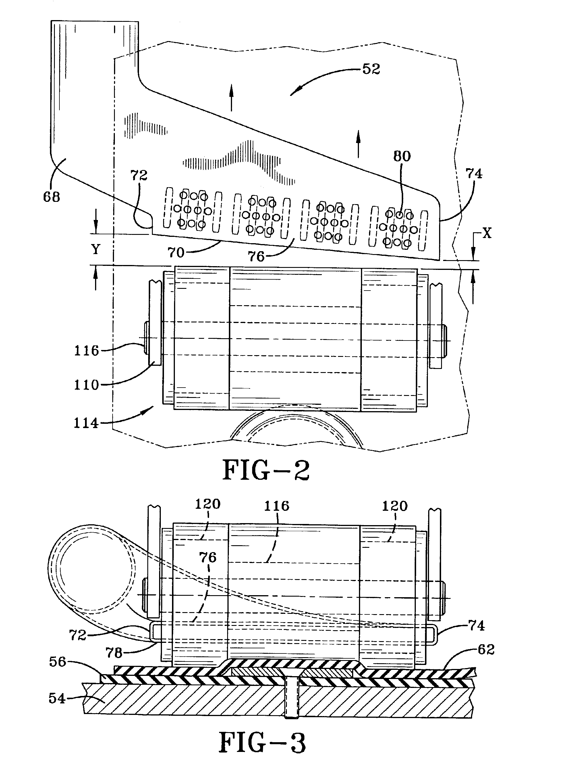
The present invention provides an apparatus for seam welding membranes that avoids obstructions and creates a continuous width weld when obstructions are not present. The apparatus includes a wheeled carriage, heating assembly, and roller assembly. The heating assembly uses a nozzle to provide an optimal heat gradient for bonding the membranes, while the roller assembly exerts uniform pressure upon the membranes to ensure their bonding to one another. The pressure roller has a deflectable outer surface that allows for the formation of a substantially continuous width seam except where interrupted by a protruding fastener. The invention also provides an improved method for fusing two membranes to one another while improving the integrity of the seam.

Problems solved by technology

The welding process is complicated by the presence of the fastener along the edge of the bottom membrane.
As such, it is difficult to obtain a uniform and continuous seam / weld between the adjoining membranes.
Although effective, the disclosed seaming device is deficient inasmuch as some fastening devices do not extend along the entire edge of the membrane and a gap or bubble may form along the welded seam.
Accordingly, a secure seal is not obtained by virtue of elements infecting the gap between the seams and allows the membranes to be subjected to uplift pressures and other natural elements.
This deteriorates the integrity of the seam which ultimately damages the underlying structure.

Method used


Image

  • Obstruction avoidance continuous seam welding system
  • Obstruction avoidance continuous seam welding system
  • Obstruction avoidance continuous seam welding system

Examples


Embodiment Construction

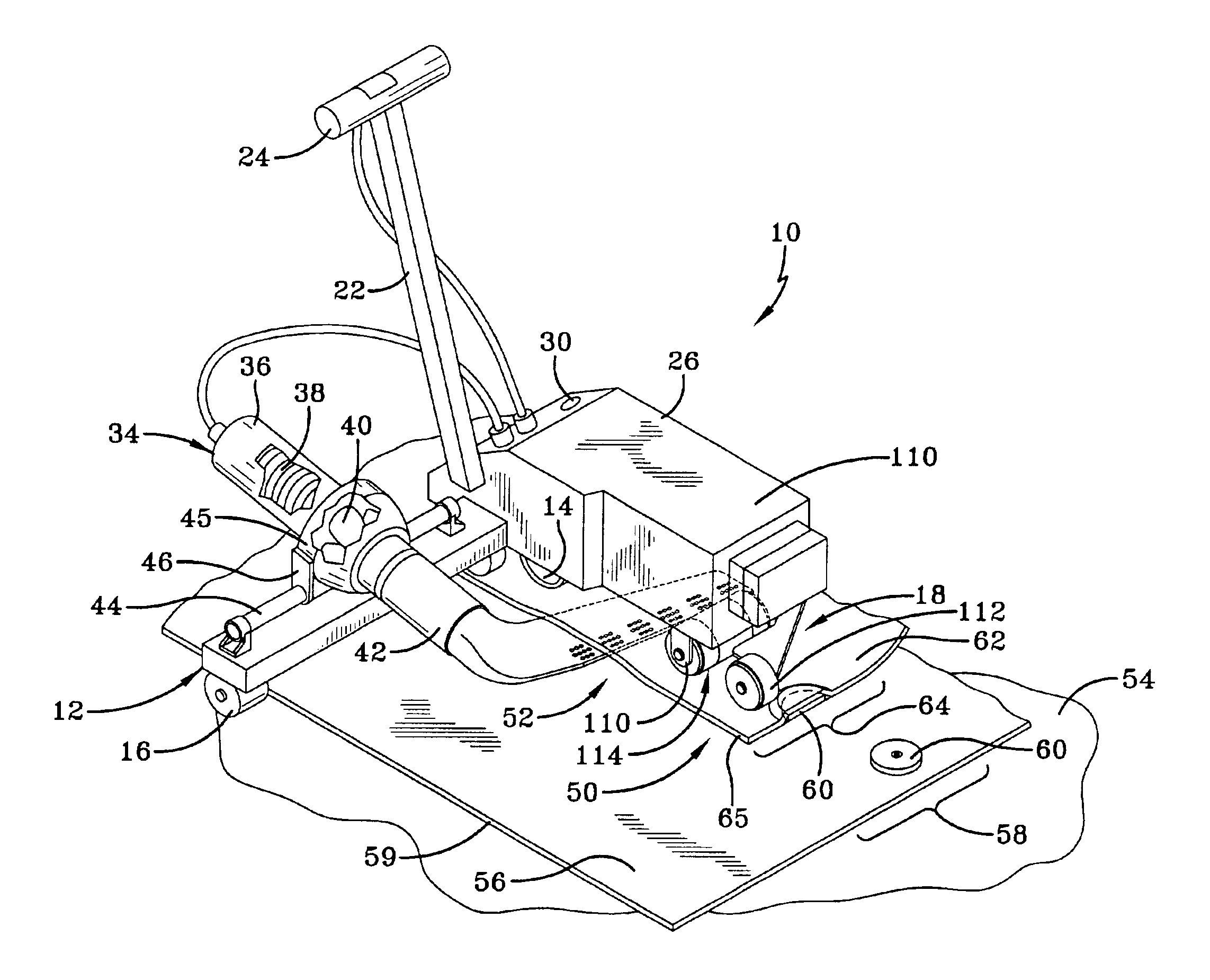
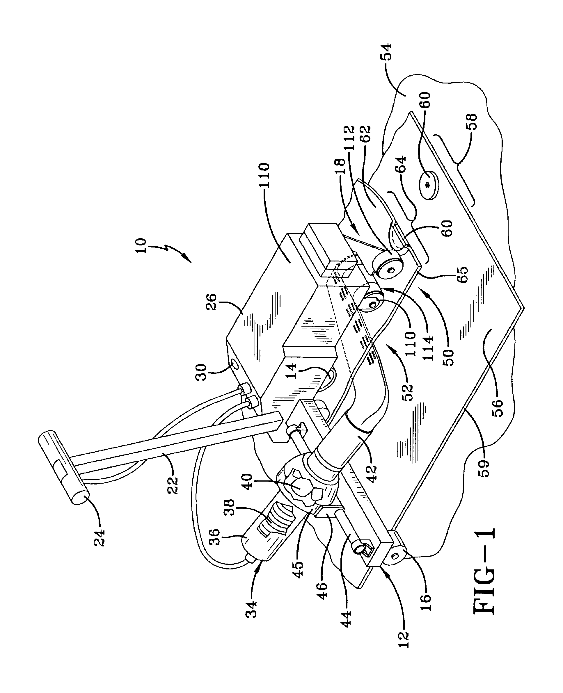
[0019]Referring now to FIG. 1, an apparatus for an obstruction avoidance continuous seam welding system is designated generally by the numeral 10. The apparatus 10 includes a carriage 12 which is supported and moveable upon a drive wheel assembly 14. Typically, the drive wheel assembly is located on the side of the carriage 12 in the direction in which the carriage is intended to move. Other wheels 16 may be positioned upon the carriage to rotatably support it during operation. Positioned at the other end of the carriage 12 is a pressure roller assembly designated generally by the numeral 18. The pressure roller assembly facilitates movement of the carriage and its full function will be described in detail hereinbelow. A shaft 22 is fixedly mounted to the carriage 12 and extends upwardly therefrom. A cross-bar 24 extends perpendicularly from the shaft 22 and may be employed by an operator to push or pull the carriage.

[0020]The carriage 12 carries a power supply 26 which may be an el...


PUM

PropertyMeasurementUnit
hardnessaaaaaaaaaa
diameteraaaaaaaaaa
lengthaaaaaaaaaa

Abstract

An apparatus for seaming roofing membranes to one another, wherein one of the membranes is secured to an underlying support structure by at least one protruding fastener is provided. The apparatus includes a wheeled carriage having an upwardly extending push / pull bar. A power supply propels the wheeled carriage and energizes a heating assembly that generates a heated airflow sufficient to fuse the roofing membranes to one another. A nozzle is coupled to the heating assembly for directing the heated airflow between the two membranes. A variable pressure roller assembly is coupled to the carriage and has a single durometer material carried by an axle that may have different diameter sections. The roller passes over the at least one protruding fastener while still applying a uniform pressure so as to form a substantially continuous width seam except where interrupted by the protruding fastener.

Description

[0001]This application claims the benefit of U.S. Provisional Application No. 60 / 380,500, filed May 13, 2002.FIELD OF THE INVENTION[0002]This invention relates generally to roof membrane seam welders. More particularly, it relates to a seam welder that accommodates fastening obstructions and provides a continuous seam weld when obstructions are not present.BACKGROUND OF THE INVENTION[0003]When installing a roof, roof membranes are applied over the base structure. Roof membranes, which are made of polymeric materials such as ethylene propylene diene monomer (EPDM), repel water, snow, and generally protect the integrity of the underlying structure.[0004]To properly install roof membranes, a fastening device such as a plate, batten bar, or other type of mechanical affixment secures one edge of a membrane to the underlying structure. An edge of a second membrane is then placed over the first membrane and the fastening device. The membranes are then welded to one another by applying a so...

Claims


Application Information

Patent Timeline
Patent Type & Authority Patents(United States)
IPC IPC(8): B29C65/00B29C65/10E04D15/04
CPCB29C66/1122B29C66/43B29C66/80B29C66/81457B29C66/8362B29C66/8652E04D15/04B29C65/103B29C66/342B29C66/86521B29C66/435B29K2023/16B29L2031/108B29C66/71B29C66/73921B29C66/73941B29C66/81241B29C66/81264B29C66/8248B29C66/8618B29K2995/007
Inventor HENEGAR, JEFFREY W.
Owner FIRESTONE BUILDING PRODS
Learn More