
Memory module controller for providing an interface between a system memory controller and a plurality of memory devices on a memory module

a memory module and controller technology, applied in the field of memory systems, can solve the problems of reducing the maximum operating frequency, increasing power consumption, and reducing the performance of the system

Inactive Publication Date: 2005-11-29
INTEL CORP
View PDF19 Cites 238 Cited by
  • Summary
  • Abstract
  • Description
  • Claims
  • Application Information

AI Technical Summary

Problems solved by technology

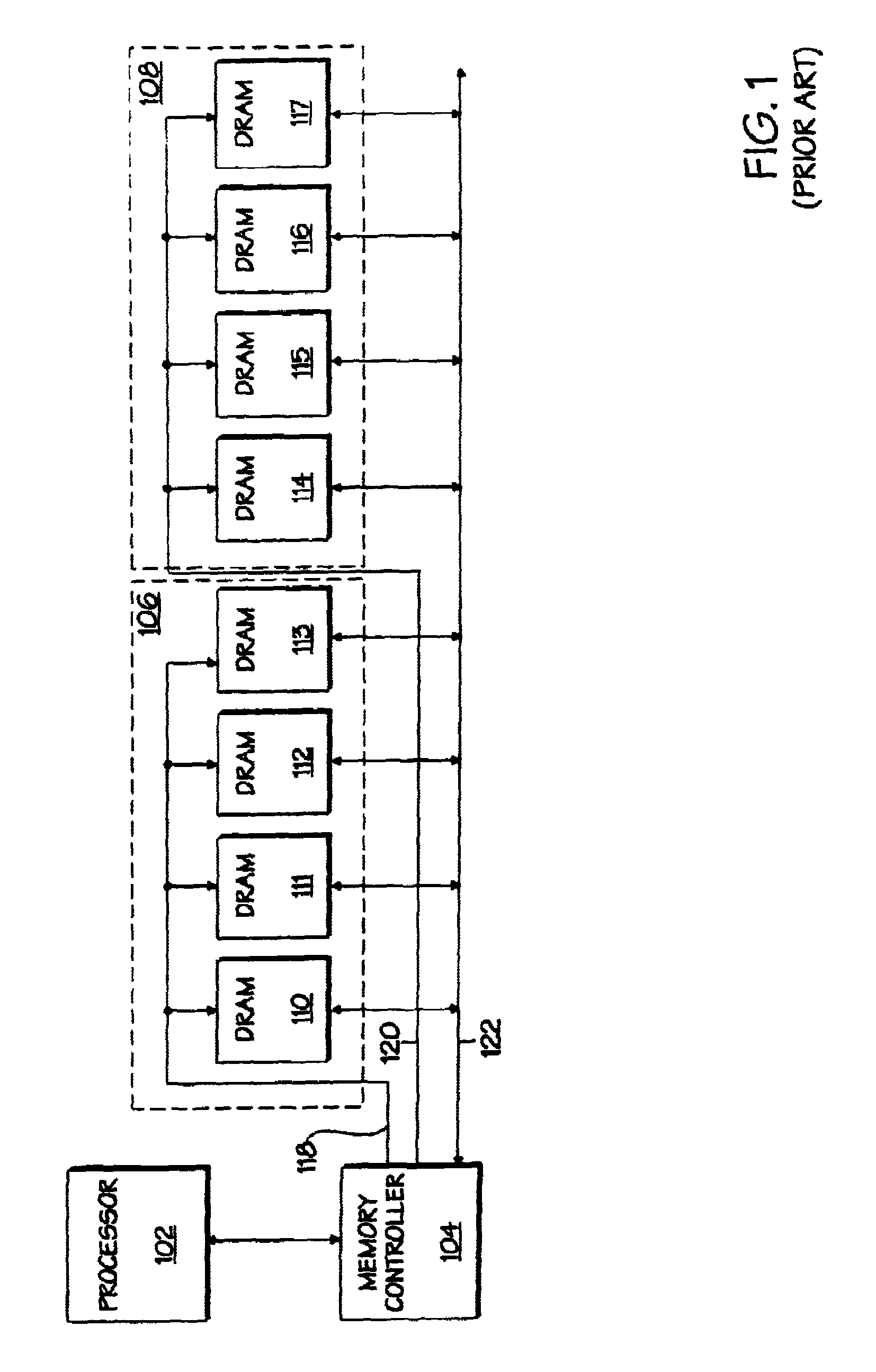
These disadvantages combine to reduce the maximum operating frequency, increase power consumption, and decrease performance of the system.
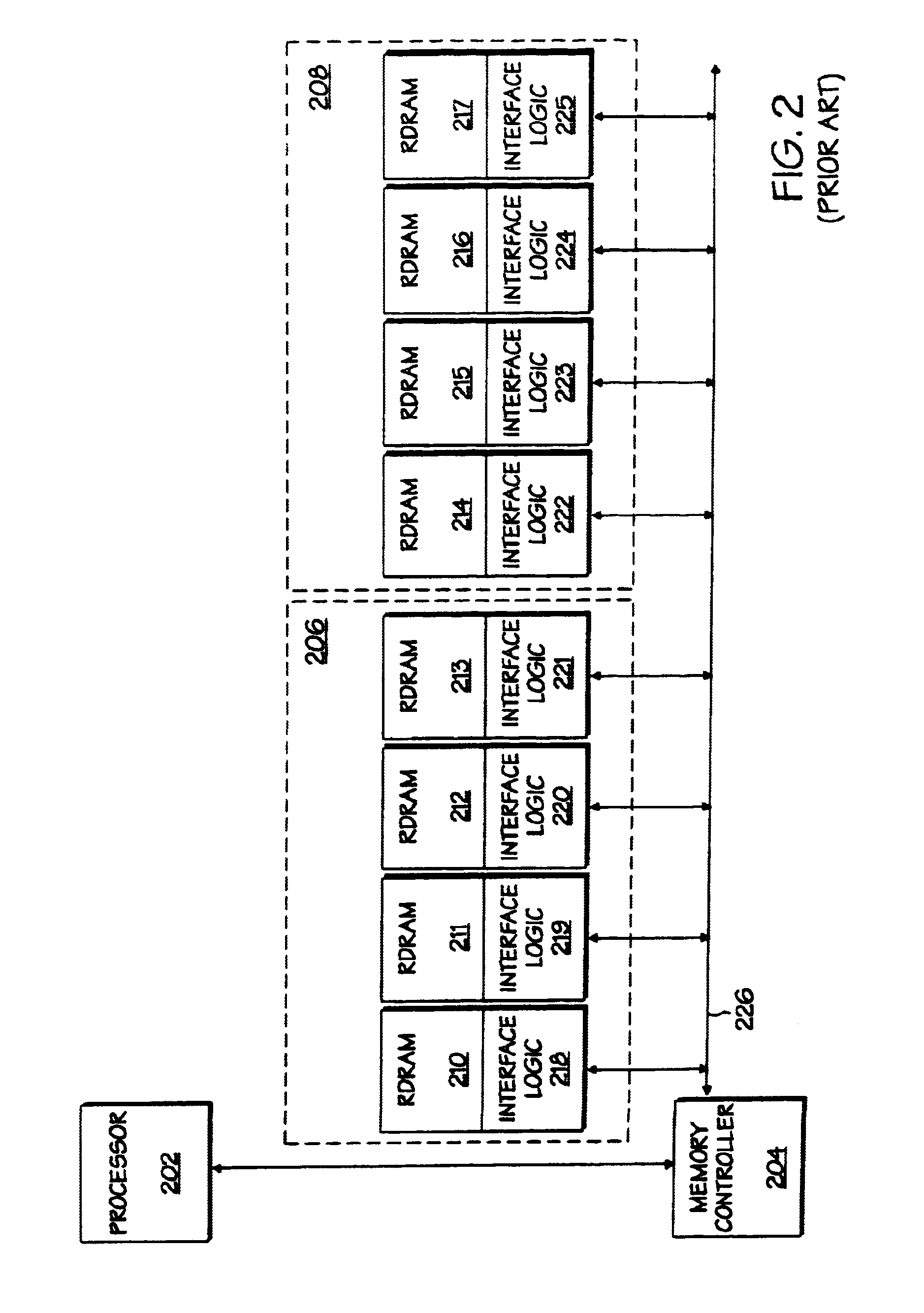
Each RDRAM™ device includes a significant amount of logic in the interface logic which makes implementation of the RDRAM™ devices more difficult and more expensive than other DRAM devices, and which causes the RDRAM™ devices to draw more power and dissipate more heat than if the logic was not present.
This may lead to thermal and reliability problems.
The DLL circuits are typically always functioning and drawing significant amounts of power which contributes to thermal and reliability issues.

Method used


Image

  • Memory module controller for providing an interface between a system memory controller and a plurality of memory devices on a memory module
  • Memory module controller for providing an interface between a system memory controller and a plurality of memory devices on a memory module
  • Memory module controller for providing an interface between a system memory controller and a plurality of memory devices on a memory module

Examples


Embodiment Construction

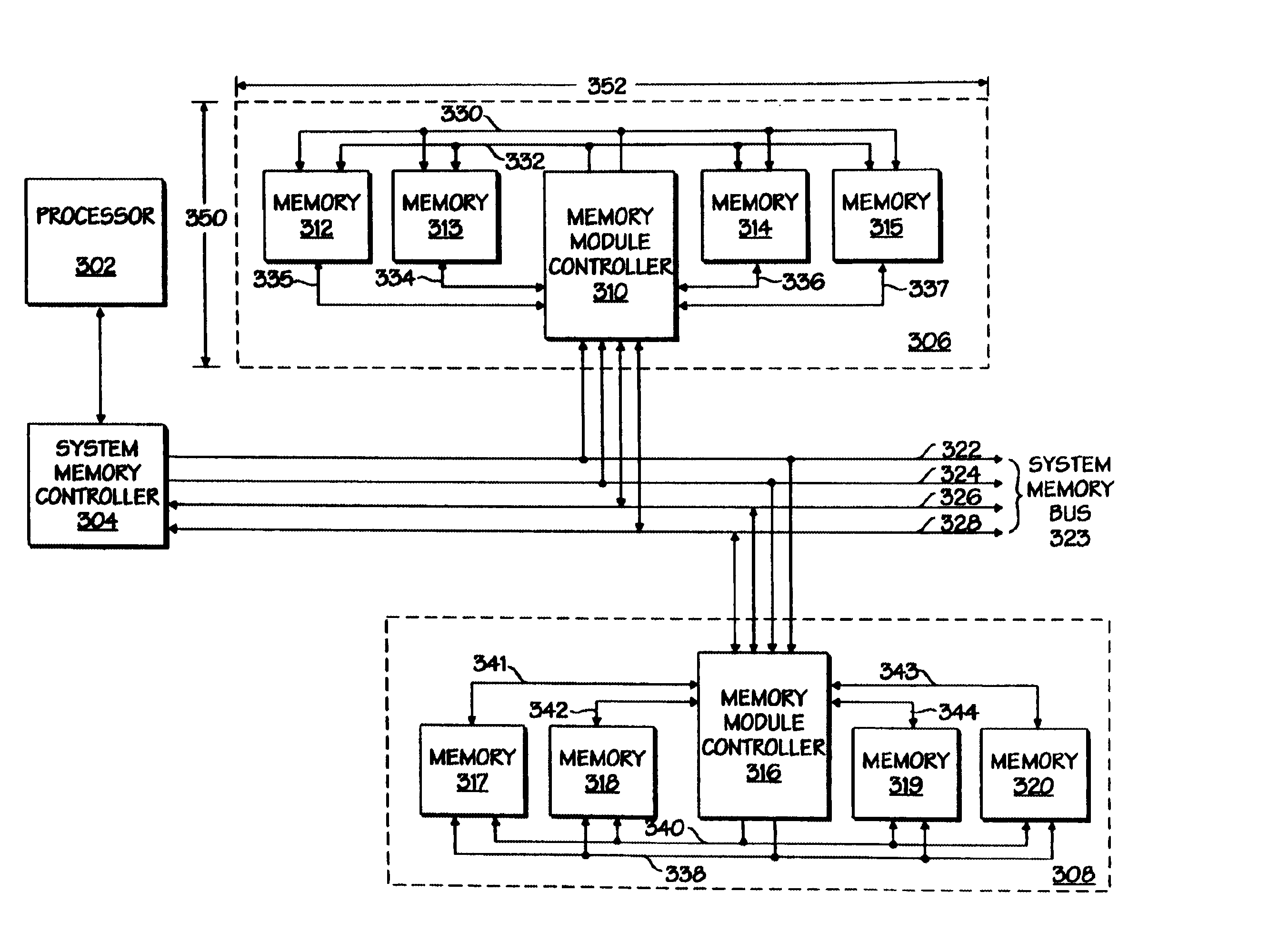
[0031]A memory system including distributed control of memory devices on memory modules is described. The present invention includes a memory module controller device on each memory module in the system. The memory module controller communicates with the system memory controller over a system memory bus and with the individual memory devices at the module level. The system memory bus may be a low pin count, high frequency, multiplexed or demultiplexed bus. The memory module controller may communicate with the individual memory devices over wider, lower frequency, demultiplexed signals lines. As the system memory controller communicates directly with only the memory module controllers, the loading on the system memory bus may be reduced and the size of the bus drivers in the system memory controller may also be reduced.

[0032]The memory module controller on each memory module is the interface between the system memory controller and the individual memory devices on the modules. This a...


PUM


Abstract

A memory module controller for providing interface between a system memory controller and a plurality of memory devices on a memory module. The memory module includes first interface circuitry and control logic. The first interface circuitry is configured to receive from the system memory controller a first memory transaction in a first format. The control logic is coupled to the first interface circuitry and configured to convert the first memory transaction into a second memory transaction in a second format for the plurality of memory devices. The second format of the second memory transaction is different than the first format of the first memory transaction.

Description

RELATED APPLICATIONS[0001]This application is related to and claims the benefit of the filing dates of the following U.S. Provisional Patent Applications: (1) Provisional Application No. 60 / 067,824, entitled DISTRIBUTED CONTROL MEMORY BUS ARCHITECTURE, filed on Dec. 5, 1997; and (2) Provisional Application No. 60 / 067,588, entitled DISTRIBUTED CONTROL MEMORY BUS ARCHITECTURE, filed on Dec. 5, 1997. These applications are assigned to the same assignee as the present application.[0002]This application is also related to U.S. patent application Ser. No. 09 / 023,170, entitled MEMORY MODULE SYSTEM INCLUDING A MEMORY MODULE HAVING A MEMORY MODULE CONTROLLER filed on Feb. 13, 1998, and U.S. patent application Ser. No. 09 / 023,234, titled MEMORY MODULE INCLUDING A MEMORY MODULE CONTROLLER filed on Feb. 13, 1998, each of which is assigned to the assignee of the present application.FIELD OF THE INVENTION[0003]The present invention pertains to the field of memory systems. More particularly, the p...

Claims


Application Information

Patent Timeline
IPC IPC(8): G06F13/16
CPCG06F13/1694
Inventor HOLMAN, THOMAS J.
Owner INTEL CORP
Learn More