
Air conditioner with dehumidifying and heating operation

a technology of air conditioner and heating operation, which is applied in the direction of heating types, domestic cooling devices, lighting and heating devices, etc., can solve the problems of air to be blown into the passenger compartment that is not sufficiently heated, the heat absorption amount in the exterior heat exchanger is reduced, and the heat absorbing operation cannot be performed in the exterior heat exchanger, etc., to achieve sufficient heating capacity and sufficient dehumidification

Active Publication Date: 2005-11-22
DENSO CORP
View PDF5 Cites 17 Cited by
  • Summary
  • Abstract
  • Description
  • Claims
  • Application Information

AI Technical Summary

Benefits of technology

The present invention provides an air conditioner that can dehumidify air while increasing heating capacity. The air conditioner includes a compressor, heat exchangers, and decompression devices. A circulation means is provided for circulating refrigerant between the heat exchangers and the decompression devices. The air conditioner can switch between a first circulation state and a second circulation state to effectively heat and dehumidify the passenger compartment of a vehicle. The technical effects of the invention include improved air conditioning efficiency and increased comfort for passengers.

Problems solved by technology

However, if the dehumidifying and heating operation is performed when an outside air temperature is lower than 0° C., that is, when an air conditioning load (heating load) is large, the following problems occur.
Accordingly, when the outside air temperature is low, a heat absorption amount in the exterior heat exchanger is reduced due to a decrease of an outside air temperature, and a heat absorbing operation cannot be performed in the exterior heat exchanger.
As a result, air to be blown into a passenger compartment may be not sufficiently heated.

Method used


Image

  • Air conditioner with dehumidifying and heating operation
  • Air conditioner with dehumidifying and heating operation
  • Air conditioner with dehumidifying and heating operation

Examples


first embodiment

[0022](First Embodiment)

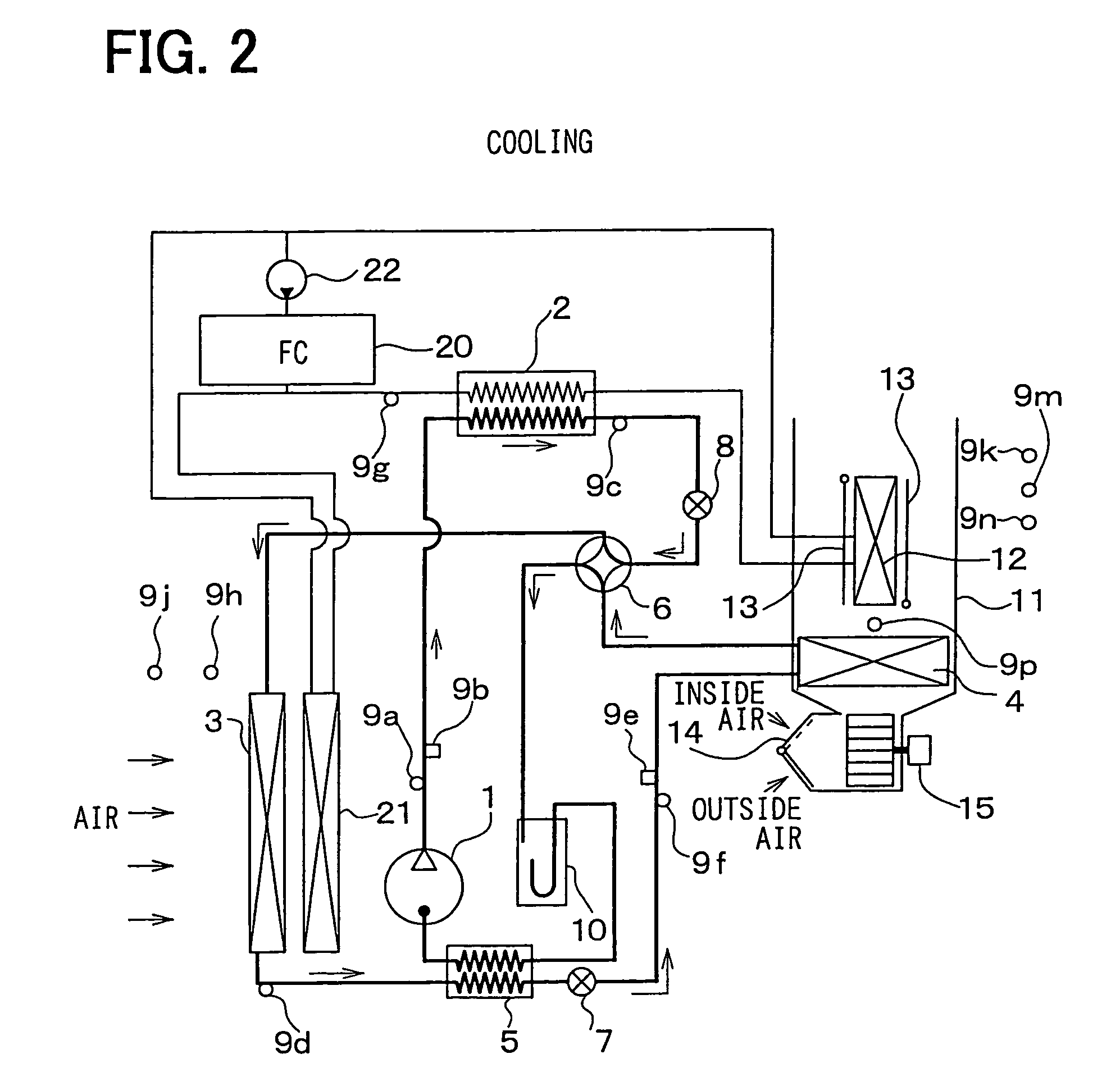
[0023]The first embodiment of the present invention will be now described with reference to FIGS. 1A–6B. In the first embodiment, a vapor-compression refrigerant cycle of the present invention is typically applied to an air conditioner for an electric vehicle. In the vapor-compression refrigerant cycle, carbon dioxide is used as refrigerant.

[0024]In the electric vehicle, a fuel cell (FC stack) 20 shown in FIG. 1A generates electric power by using a chemical reaction between oxygen and hydrogen, and the generated electric power is supplied to an electric motor (not shown) for running the electric vehicle. In FIG. 1A, a radiator 21 is a heat exchanger that cools cooling water for heating or cooling the fuel cell 20 by performing a heat exchange between the cooling water and outside air. A pump 22 is an electric pump for pumping and circulating the cooling water in a cooling water circuit.

[0025]A compressor 1 sucks and compresses refrigerant. In this embodiment,...

second embodiment

[0058](Second Embodiment)

[0059]In the above-described first embodiment, heat of high-temperature refrigerant discharged from the compressor 1 is supplied to cooling water flowing into the heater 12, in the first exterior heat exchanger 2. In this way, the heat is indirectly supplied to air to be blown into the passenger compartment. However, in the second embodiment, as shown in FIG. 7, the heat of the high-temperature refrigerant discharged from the compressor 1 is directly supplied to air to be blown into the passenger compartment, without through a medium such as cooling water. Accordingly, when the second dehumidifying and heating operation is set, refrigerant discharged from the compressor 1 flows into the heater 12 (heat exchanger 2) disposed in the air conditioning case 11. Therefore, air passing through the heater 2 can be directly heated by the high-temperature refrigerant discharged from the compressor 1. Refrigerant flowing from the heater 12 (heat exchanger 2) is decompr...


PUM


Abstract

When a dehumidifying and heating operation is set in an air conditioner, refrigerant is circulated from a compressor to the compressor through a first exterior heat exchanger, a decompression device, an interior heat exchanger, an another decompression device, an inner heat exchanger and a second exterior heat exchanger, in this order. Further, by controlling a throttle opening degree of the another decompression device, a refrigerant temperature in the interior heat exchanger can be set higher than that in the second exterior heat exchanger. Thus, even when the interior heat exchanger is controlled to a temperature to be not frosted, heat can be absorbed from outside air in the second exterior heat exchanger. Accordingly, when an outside air temperature is low, by setting the dehumidifying and heating operation, air to be blown into a compartment can be dehumidified while sufficiently increasing heating capacity.

Description

CROSS-REFERENCE TO RELATED APPLICATION[0001]This application is related to and claims priority from Japanese Patent Application No. 2003-3263 filed on Jan. 9, 2003, the content of which is hereby incorporated by reference.FIELD OF THE INVENTION[0002]The present invention relates to an air conditioner with a dehumidifying and heating operation. The air conditioner of the present invention is effectively used for an electric vehicle.BACKGROUND OF THE INVENTION[0003]In an air conditioner disclosed in U.S. Pat. No. 5,526,650 (corresponding to JP-A-8-40056), when a dehumidifying and heating operation is performed, high pressure refrigerant discharged from a compressor is circulated into a first interior heat exchanger to heat air to be blown into a passenger compartment. Then, refrigerant flowing out of the first interior heat exchanger is decompressed, and the decompressed refrigerant is circulated into an exterior heat exchanger and a second interior heat exchanger in this order, so th...

Claims


Application Information

Patent Timeline
Patent Type & Authority Patents(United States)
IPC IPC(8): B60H1/00F25B13/00F25B9/00F24F3/153F24F3/12F25B40/00F25B40/04B60H1/22B60H1/32B60H3/00F25B1/00
CPCB60H1/00392B60H1/00735B60H1/00907B60H1/3213F24F3/153F25B9/008F25B13/00B60H2001/00928B60H2001/00935B60H2001/00957B60H2001/3244B60H2001/3248B60H2001/325B60H2001/3255B60H2001/3257B60H2001/3285F25B40/00F25B40/04F25B2309/061F25B2313/004F25B2313/02341F25B2313/02344F25B2313/02541F25B2313/0312F25B2313/0314F25B2313/0315F25B2341/0662F25B2500/02F25B2500/31F25B2700/02F25B2700/1931F25B2700/2104F25B2700/2106F25B2700/21152F25B41/39
Inventor ITOH, SATOSHIYAMAGUCHI, MOTOHIRO
Owner DENSO CORP
Learn More