Method for securing a polishing pad to a platen for use in chemical-mechanical polishing of wafers

a technology of chemical-mechanical polishing and polishing pad, which is applied in the field of material polishing, can solve the problems of increasing the changeover time, operator personal injury, and complex mechanism, and achieves the effects of improving safety, speeding up the changeover time, and avoiding undue stress and tim

Inactive Publication Date: 2005-11-15
RAYBESTOS POWERTRAIN
View PDF11 Cites 0 Cited by
  • Summary
  • Abstract
  • Description
  • Claims
  • Application Information

AI Technical Summary

Benefits of technology

[0006]It is, therefore, the primary objective to provide a securing layer for releasably, yet strongly, attaching a polishing pad to a CMP platen, which securing layer does not require adhesives, so that the polishing pad may be removed from the platen via the securing layer without undue stress and time.

Problems solved by technology

These mechanisms are complex; however, in general the slurry contains chemicals that react with the deposited layer on the wafer, abrasives that mechanically cut (micro-machine) the layer, and complexing agents that prevent the removed material from precipitating or re-depositing on the wafer surface.
Since typical PSA materials have high peel strength, it can require significant force to overcome the pressure-sensitive-adhesive adhesion, thus increasing the changeover time.
In addition, the operator could experience personal injury due to the poor ergonomics of the process, especially if the pad is stiff.
However, these prior-art improvements require either external equipment or modification to the machine and / or platen.

Method used


Image

  • Method for securing a polishing pad to a platen for use in chemical-mechanical polishing of wafers
  • Method for securing a polishing pad to a platen for use in chemical-mechanical polishing of wafers
  • Method for securing a polishing pad to a platen for use in chemical-mechanical polishing of wafers

Examples


Embodiment Construction

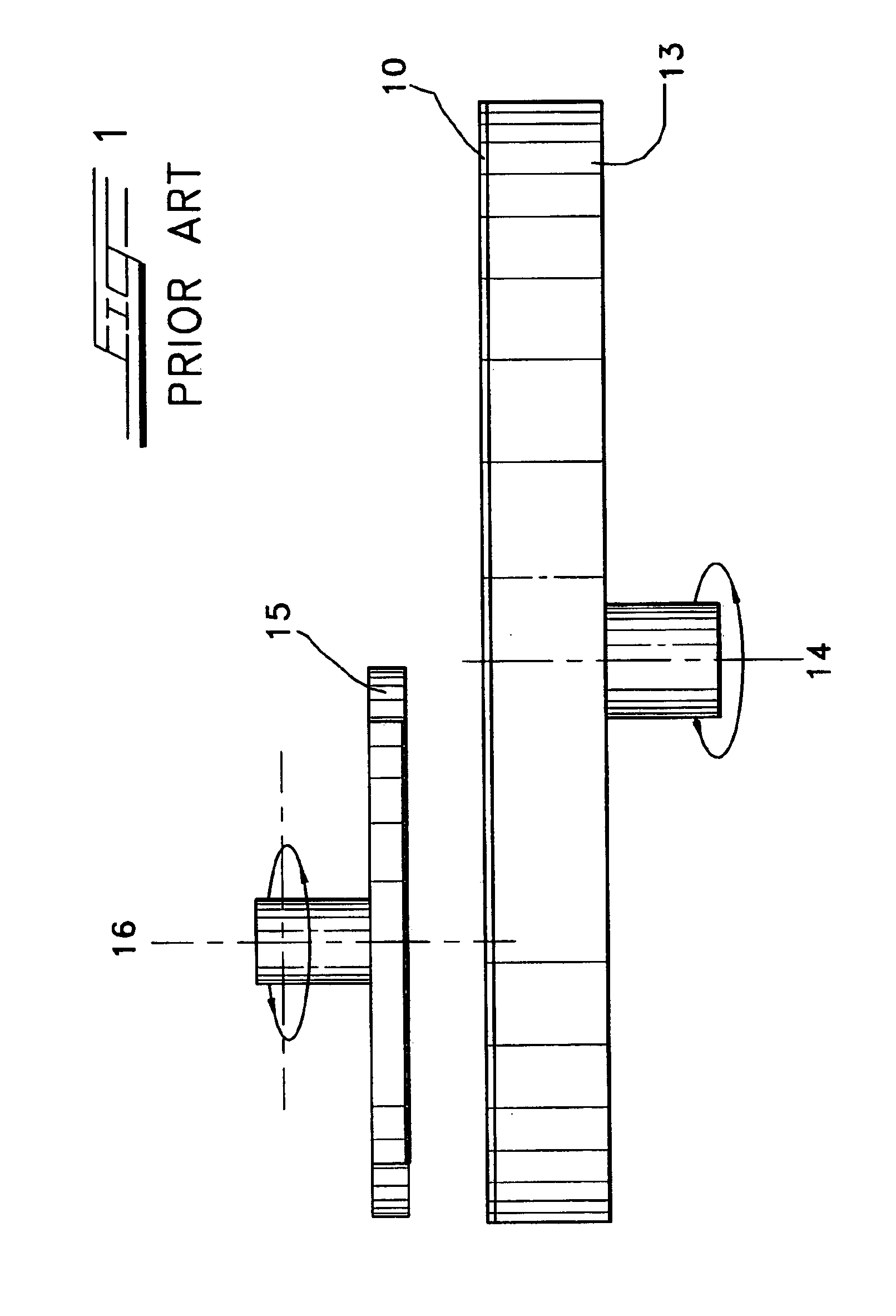
[0014]Referring now to the drawings in greater detail, a typical CMP apparatus is shown in FIG. 1. A polishing pad 10 is affixed to a platen 13 that rotates about a fixed axis 14. The wafer to be polished is affixed to a carrier 15 that rotates about a fixed axis 16 which is offset from the platen's fixed axis 14 but which rotates in the same direction. The carrier 15 usually scans the surface of the pad 10 along axis 16 while applying downward pressure on the wafer during polishing. During the polishing process, a polishing slurry is introduced onto the surface of the pad. In some applications, slurry is introduced through the pad from the platen 13.

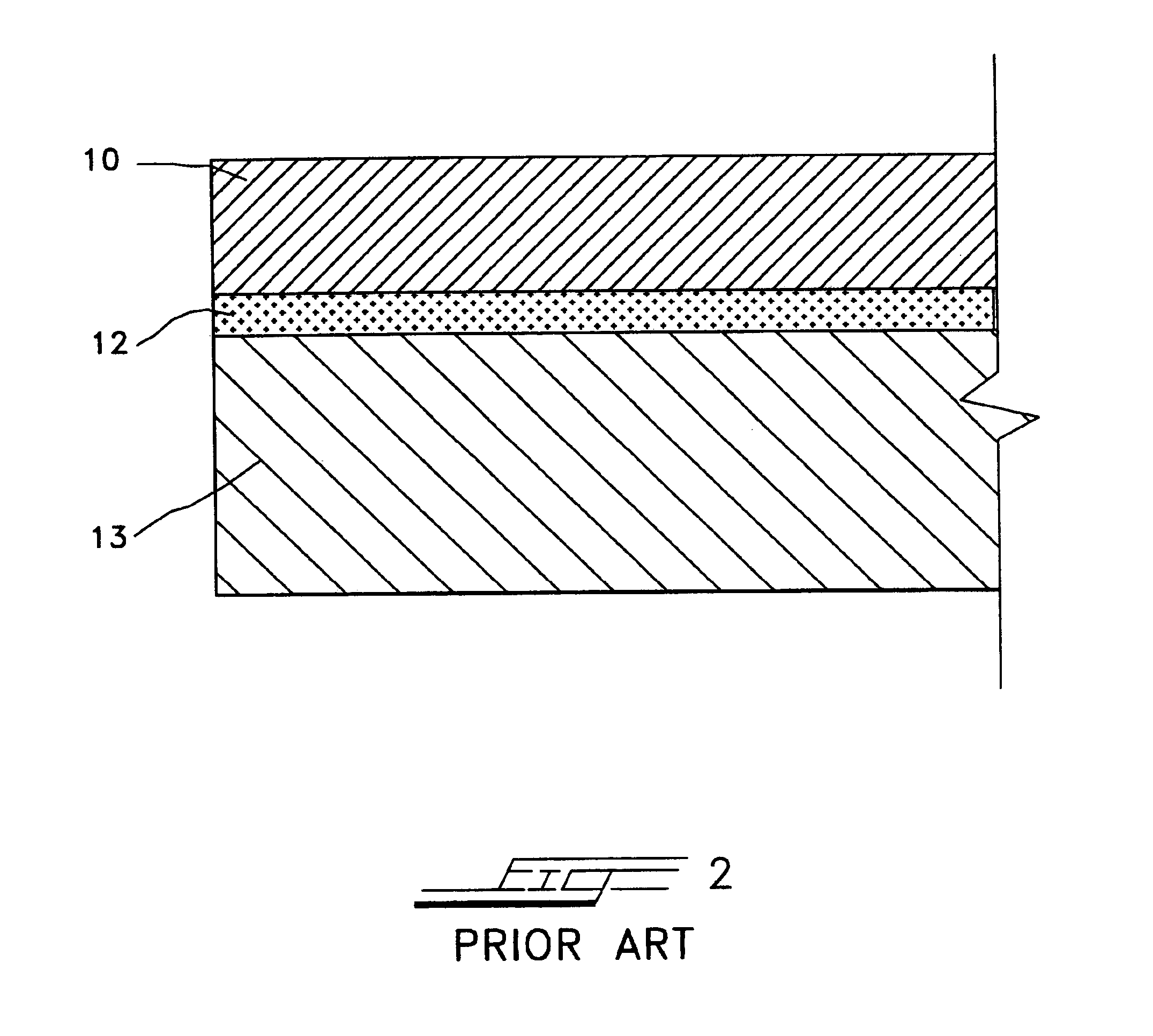
[0015]A typical, prior-art technique for securing polishing pad 10 to the platen 13 is shown in FIG. 2. The polishing pad 10 is attached to the rotating platen 13 via a pressure-sensitive adhesive (PSA) layer 12. Removal of the polishing pad is generally a difficult operation, since typical peel strengths of PSA layers tend to be quite ...


PUM

PropertyMeasurementUnit
shear strengthaaaaaaaaaa
peel strengthsaaaaaaaaaa
shear strengthsaaaaaaaaaa

Abstract

The present invention is related to a method for securing a polishing pad to the platen for use in chemical-mechanical polishing. Specifically, a polishing pad is attached to a platen using a reclosable, hook-and-pile fastener, whereby the platen-attachment fastener may be reused. Separate embodiments are disclosed for attaching porous and nonporous polishing pads.

Description

CROSS REFERENCE TO RELATED APPLICATION[0001]Priority of provisional application No. 60 / 395,433, filed on Jul. 12, 2002, is herewith claimed.BACKGROUND OF THE INVENTION[0002]The present invention is related to polishing of materials, and in particular to the chemical-mechanical polishing (CMP) of dielectric layers or integrated circuits. Specifically, the present invention is directed to a method of securing a polishing pad to a platen used in the polishing of semiconductor wafers.[0003]In the field of semiconductor manufacture, numerous integrated circuits are produced on round wafers through layers of wiring devices. During the process of forming layers and structures, the topography of the surface becomes increasingly irregular. The prevailing technology for planarizing the surface is chemical-mechanical polishing (CMP). In effect, this process planarizes the top layer of an integrated circuit prior to the depositing of another layer.[0004]In CMP processes, the working layer of an...

Claims


Application Information

Patent Timeline
Patent Type & Authority Patents(United States)
IPC IPC(8): B24B37/04B24D13/00B24D13/14B24B37/20
CPCB24B37/20
Inventor PETROSKI, ANGELACOOPER, RICHARD D.FATHAUER, PAULPERRY, DAVIDMACEY, JAMES
Owner RAYBESTOS POWERTRAIN
Why Eureka
Try Eureka