High speed bus topology for expandable systems

a computer system and bus topology technology, applied in the field of computer systems, can solve the problems of increasing system cost and module layout complexity, reducing bus length, and reducing bus length, so as to maintain a uniform transmission line impedance, reduce bus length, and increase the operating bandwidth of short-loop buses

Inactive Publication Date: 2005-11-08
MICRON TECH INC
View PDF27 Cites 8 Cited by
  • Summary
  • Abstract
  • Description
  • Claims
  • Application Information

AI Technical Summary

Benefits of technology

The present invention provides a high-speed bus topology for expandable computer systems that is shorter and has a greater operating bandwidth than prior art systems. The bus is routed through a first expansion card and out of a second expansion connector, which reduces bus length and maintains a uniform transmission line impedance. The bus is also routed in a vertical manner, which further reduces bus length and overcomes shortcomings of current bus topologies. The technical effects of the invention include increased operating bandwidth, reduced bus length, and improved transmission line impedance.

Problems solved by technology

This connection typically results in a branch off the main bus to the receiving components on the expansion card.
The stubs are electrically undesirable for high-speed buses, since they provide a discontinuity of impedance along the bus, which results in reflected energy on the bus.
There is some added system cost and module layout complexity associated with the large number of resistors.
This layout restriction becomes impractical for larger bus widths due to the congestion of the bus and due to the amount of board surface area that the bus uses.
Further, the lower bus impedance requires a lower termination resistance, which dissipates more power for a given signal voltage swing.
Another disadvantage of the loop-through system 50 is that the bus length gets very long.
The increased latency reduces the computer system performance.
Longer flight times can also reduce the efficiency of the bus B for moving information.
Otherwise, the data will be corrupted.
A similar waiting period can occur when one DRAM element releases the bus B before another DRAM element drives the bus B. If there is an existing voltage waveform propagating on the bus B this situation can result in excessively high or low voltages on the bus B when the second DRAM element drives it.
Since it is not practical to for the bus B to maintain a perfectly uniform impedance, there will also be some reflected energy travelling along the bus B. If the bus B voltage is not in a stable state when the next DRAM element drives it, the transition time of the signal moving through the reference voltage will be adversely effected.
This results in an increase or decrease in the delay of the recognition of a logical one or zero voltage.
This delay change results in timing uncertainty or timing errors, which can corrupt the data that is latched into the receiving device.
Another disadvantage of the long bus B of the loop-through bus system 50 is a reduction in maximum operating bandwidth.
Since the bus B is not physically ideal, there is attenuation and dielectric leakage in the PCB.
These losses result in a reduction of signal swing and get worse at higher frequencies.
Since there also is reflected energy travelling along the bus B, the rate at which data can be transmitted on the bus B becomes limited.
A further disadvantage of the loop-through bus system 50 is that its long bus B can increase the electromagnetic interference (EMI) of the system 50.

Method used


Image

  • High speed bus topology for expandable systems
  • High speed bus topology for expandable systems
  • High speed bus topology for expandable systems

Examples


Embodiment Construction

[0037]The present invention will be described as set forth in the preferred embodiments illustrated in FIGS. 3–11. Other embodiments may be utilized and structural or logical changes may be made without departing from the spirit or scope of the present invention. Like items are referred to by like reference numerals.

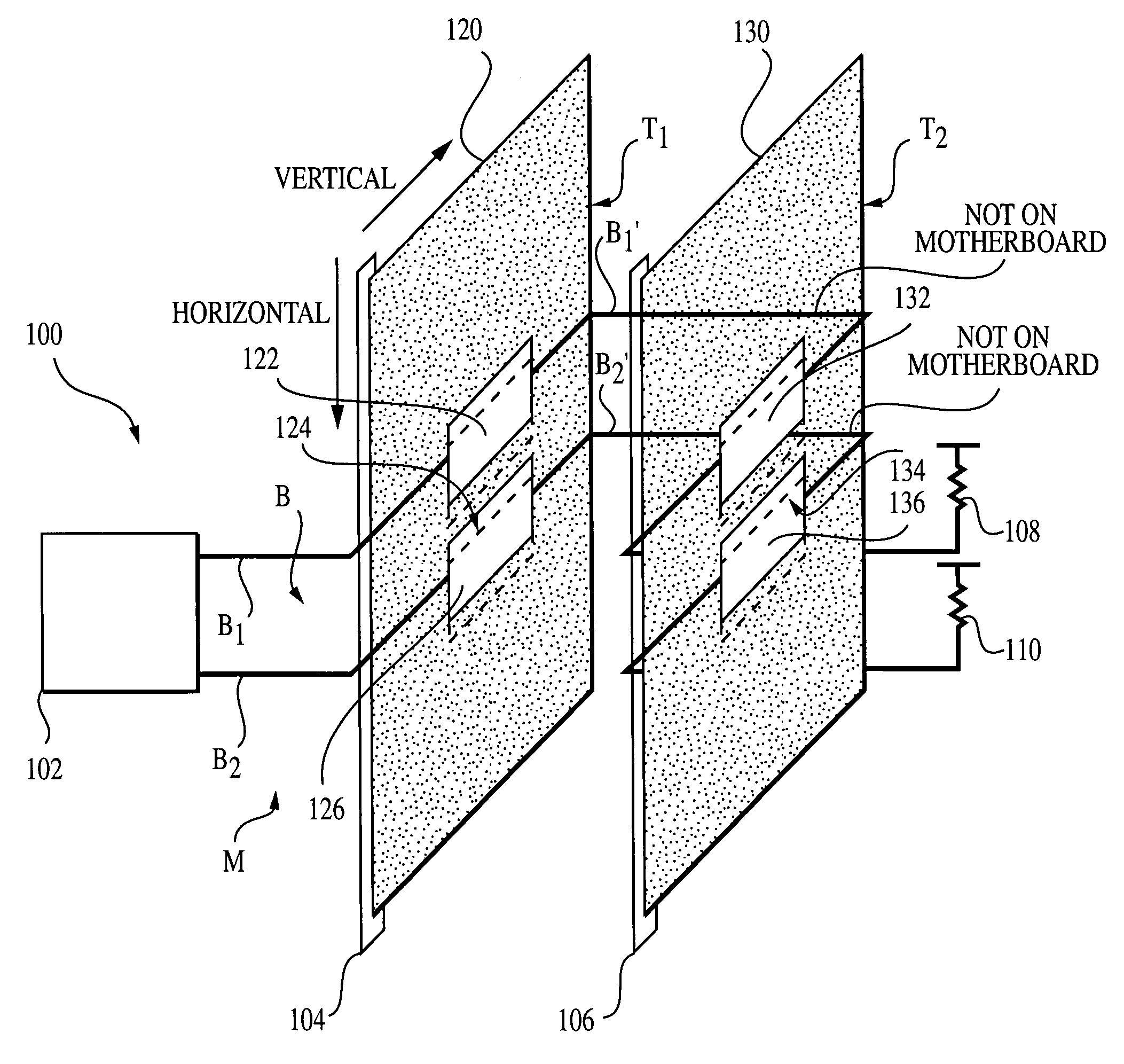
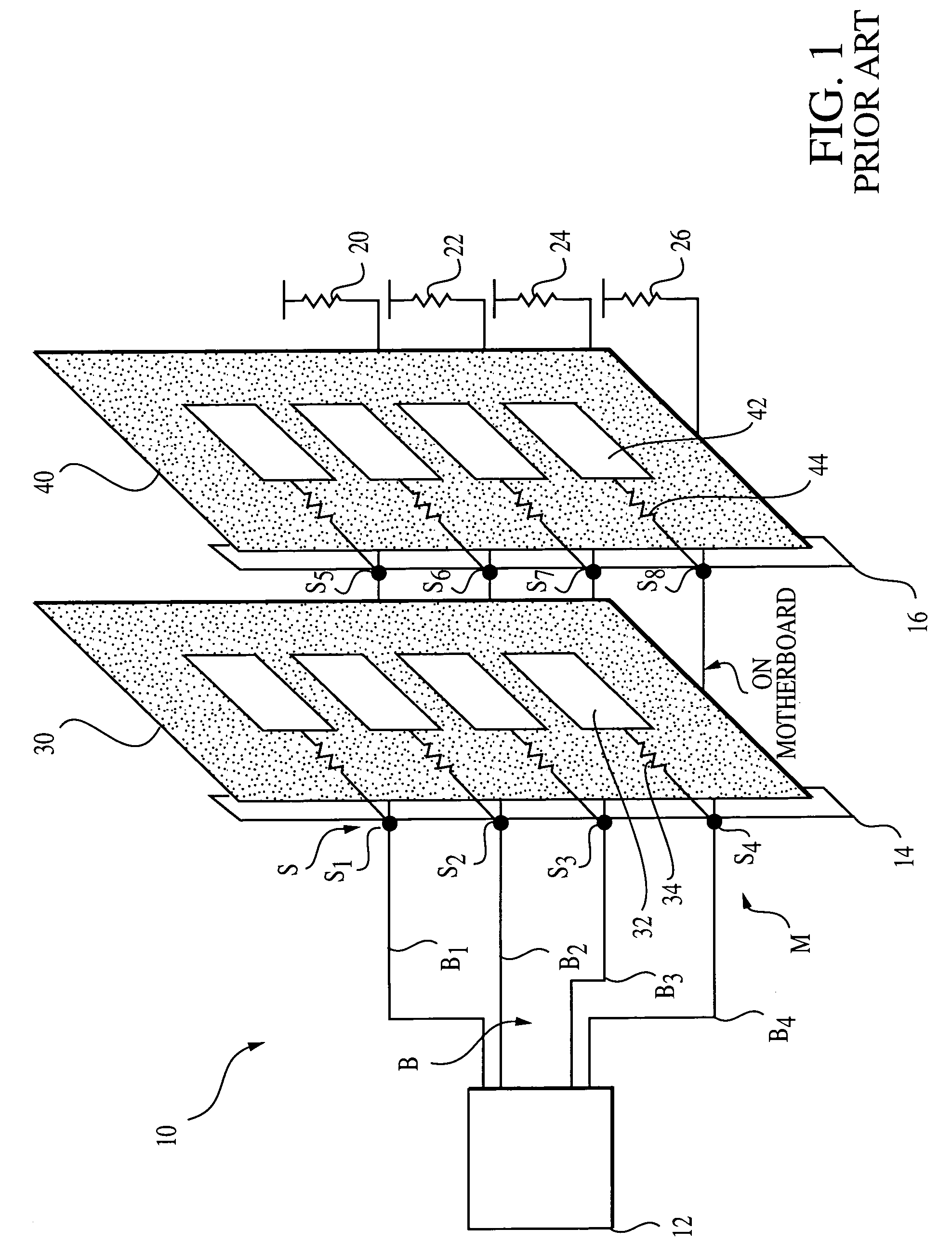
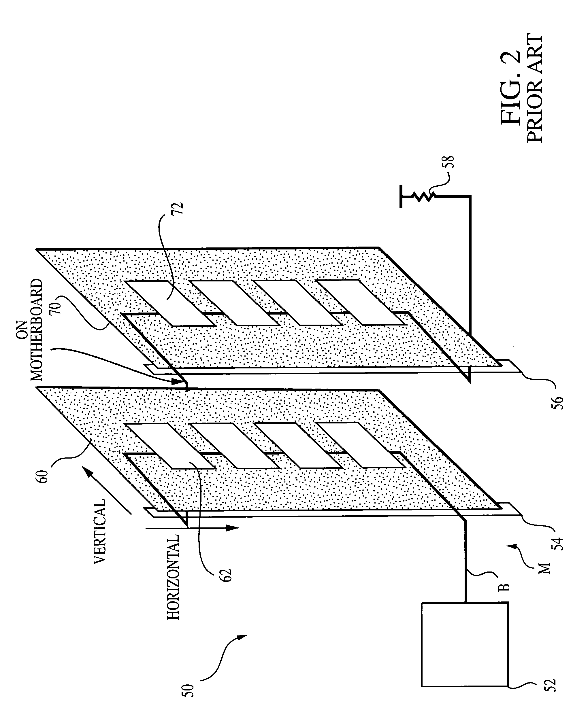
[0038]Referring to FIG. 3, a short-loop bus system 100 constructed in accordance with the present invention is illustrated. In keeping with the example used to described the prior art systems 10, 50 (FIGS. 1 and 2, respectively), the system 100 will be described as a computer main memory subsystem. It should be noted that this is just an example and that the same system 100 is appropriate for any high-speed bus having removable circuit cards.

[0039]The system 100 includes two circuit cards 120, 130 that are attached to bus lines B1, B2 through connectors 104, 106, respectively. Similar to the loop-through bus system 50 (FIG. 2), there are no stub connection points in the ...


PUM


Abstract

A high-speed short-loop bus topology that routes the bus into a first expansion connector and out of a first expansion card inserted within the connector is disclosed. The bus is not routed out of the first expansion connector. Instead, the bus is routed from the first expansion card into a second expansion card by a jumper mechanism. The bus is routed through the second expansion card and out of a second expansion connector housing the second expansion card, where the bus can be terminated or routed into another expansion connector having another expansion card. By routing the bus in this manner, it is shorter than prior art buses found in loop-through bus systems and capable of substantially maintaining a uniform transmission line impedance. Moreover, the operating bandwidth of the short-loop bus is increased since the bus is short and does not have stubs or signal reflections.

Description

BACKGROUND OF THE INVENTION[0001]1. Field of the Invention[0002]The present invention relates to the field of computer systems and, more particularly to a high speed bus topology for expandable computer systems.[0003]2. Description of the Related Art[0004]Today's computer and network systems require the ability to expand their hardware over time to improve their performance or to accommodate new users. Expansion capabilities are typically provided for graphics, input / output (I / O), network interface, microprocessors, static random access memory (SRAM) and dynamic random access memory (DRAM) circuit cards. These expansion cards are typically integrated on a printed circuit board (PCB) that can easily be inserted or removed by a user of the system. The PCB is inserted into a connector, which provides an electrical connection to a bus.[0005]The expandable bus is typically located on a host PCB, often referred to as a motherboard. Connectors are mounted on the motherboard to provide slot...

Claims


Application Information

Patent Timeline
Patent Type & Authority Patents(United States)
IPC IPC(8): G06F13/00G06F13/40H05K1/14
CPCG06F13/4095H05K1/14H05K1/145H05K2201/044
Inventor LEE, TERRY R.
Owner MICRON TECH INC
Why Eureka
Try Eureka