
Alloy type thermal fuse and wire member for a thermal fuse element

a technology of thermal fuse element and wire member, which is applied in the direction of basic electric elements, heating/cooling contact switches, emergency protection devices, etc., can solve the problems of inability to meet, the operation performance of the fuse element is inevitably changed with age, and the fuse element cannot be guaranteed to perform a predetermined operation performance, etc., to achieve low level, suppress the dispersion of operating temperature, and the effect of sufficient ductility

Inactive Publication Date: 2005-11-08
UCHIHASHI ESTEC
View PDF17 Cites 6 Cited by
  • Summary
  • Abstract
  • Description
  • Claims
  • Application Information

AI Technical Summary

Benefits of technology

"The invention provides an alloy type thermal fuse that does not contain harmful metals, has a stable operating temperature, and can be easily thinned and mechanically improved. The fuse element contains a specific alloy composition that can be adjusted to have a low specific resistance and improved mechanical characteristics. The alloy composition can also contain impurities that are inevitably produced during production. The invention also provides a wire member for a thermal fuse element that has a high liquidus temperature, a narrow temperature range, and sufficient ductility. The alloy type thermal fuse can be easily miniaturized and has improved stability to stress / strain and operating temperature."

Problems solved by technology

However, these thermal fuses contain harmful metals such as Cd and Pb, and cannot satisfy the above-mentioned requirements for environment conservation.
When this is repeated, the alloy composition of the fuse element is changed in the direction of a reduction of the amount of In, and the function of the flux is lowered, so that the operation performance of the fuse element is inevitably changed with age.
After an elapse of a long term, therefore, the fuse element cannot be assured to perform a predetermined operation performance.
In these alloys, however, the above-mentioned solid-liquid coexisting region temperature width ΔT is large, and the above-mentioned requirements such as the reduced dispersion of the operating temperature, and the operation stability to a heat cycle are hardly satisfied.

Method used


Image

  • Alloy type thermal fuse and wire member for a thermal fuse element
  • Alloy type thermal fuse and wire member for a thermal fuse element
  • Alloy type thermal fuse and wire member for a thermal fuse element

Examples


example 1

[0053]A base material of an alloy composition of 43% Sn, 6% Sb, and the balance Bi was drawn into a wire of 300 μmφ in diameter. The draw-down ratio per dice was 6.5%, and the drawing speed was 45 m / min. In the wire, no breakage occurred.

[0054]The specific resistance of the wire was measured. As a result, the specific resistance was 37 μΩ·cm.

[0055]The liquidus temperature of the wire was 148° C., and the solid-liquid coexisting region temperature width ΔT was 3° C.

[0056]Substrate type thermal fuses were produced, and the change in resistance of a fuse element in heat cycles was measured. As a result, the change in resistance was not observed, and the thermal fuses exhibited stable thermal resistance.

[0057]The operating temperatures of the thermal fuses were 147° C.±0.5° C., and the dispersion of the temperature was very small.

example 2

[0058]A base material of an alloy composition of 43% Sn, 3% Sb, and the balance Bi was drawn into a wire of 300 μmφ in diameter. The draw-down ratio per dice was 6.5%, and the drawing speed was 45 m / min. In the wire, no breakage occurred.

[0059]The specific resistance of the wire was measured. As a result, the specific resistance was 36 μΩ·cm.

[0060]The liquidus temperature of the wire was 144° C., and the solid-liquid coexisting region temperature width ΔT was 3° C.

[0061]Substrate type thermal fuses were produced, and the change in resistance of a fuse element in heat cycles was measured. As a result, the change in resistance was not observed, and the thermal fuses exhibited stable thermal resistance.

[0062]The operating temperatures of the thermal fuses were 143° C.±0.5° C., and the dispersion of the temperature was very small.

example 3

[0063]A base material of an alloy composition of 43% Sn, 9% Sb, and the balance Bi was drawn into a wire of 300 μmφ in diameter. The draw-down ratio per dice was 6.5%, and the drawing speed was 45 m / min. In the wire, no breakage occurred.

[0064]The specific resistance of the wire was measured. As a result, the specific resistance was 39 μΩ·cm.

[0065]The liquidus temperature of the wire was 152° C., and the solid-liquid coexisting region temperature width ΔT was 4° C.

[0066]Substrate type thermal fuses were produced, and the change in resistance of a fuse element in heat cycles was measured. As a result, the change in resistance was not observed, and the thermal fuses exhibited stable thermal resistance.

[0067]The operating temperatures of the thermal fuses were 150° C.±1° C., and the dispersion of the temperature was very small.


PUM

PropertyMeasurementUnit
diameteraaaaaaaaaa
operating temperatureaaaaaaaaaa

Abstract

The invention relates to an alloy type thermal fuse and a wire member for a thermal fuse element, and provides an alloy type thermal fuse in which a fuse element does not contain a harmful metal, the operating temperature is about 150° C., the dispersion of the operating temperature can be sufficiently suppressed, and the operation stability to a heat cycle can be satisfactorily assured. The thermal fuse has an alloy composition of 30 to 70% Sn, 0.3 to 20% Sb, and a balance Bi.

Description

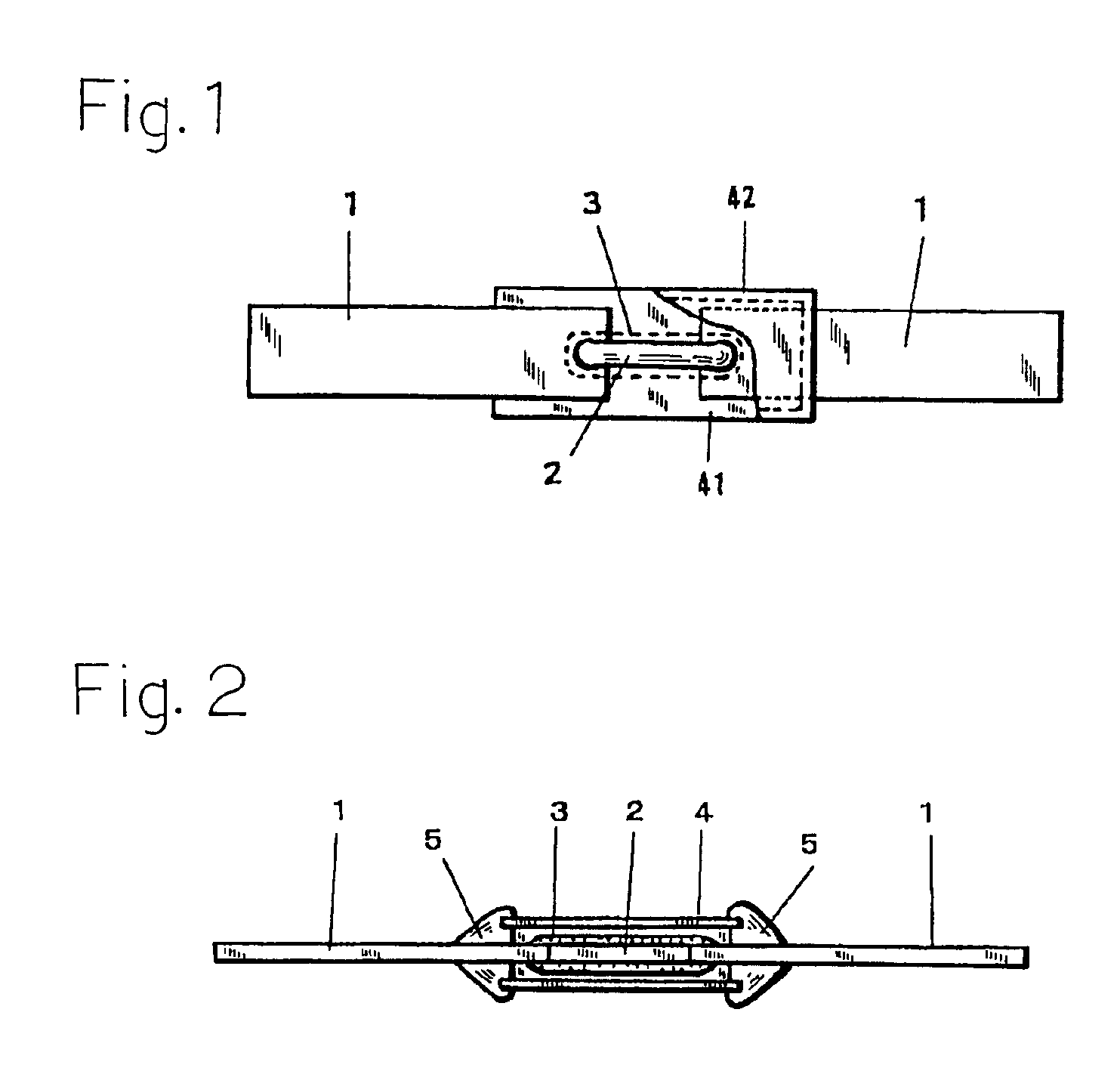
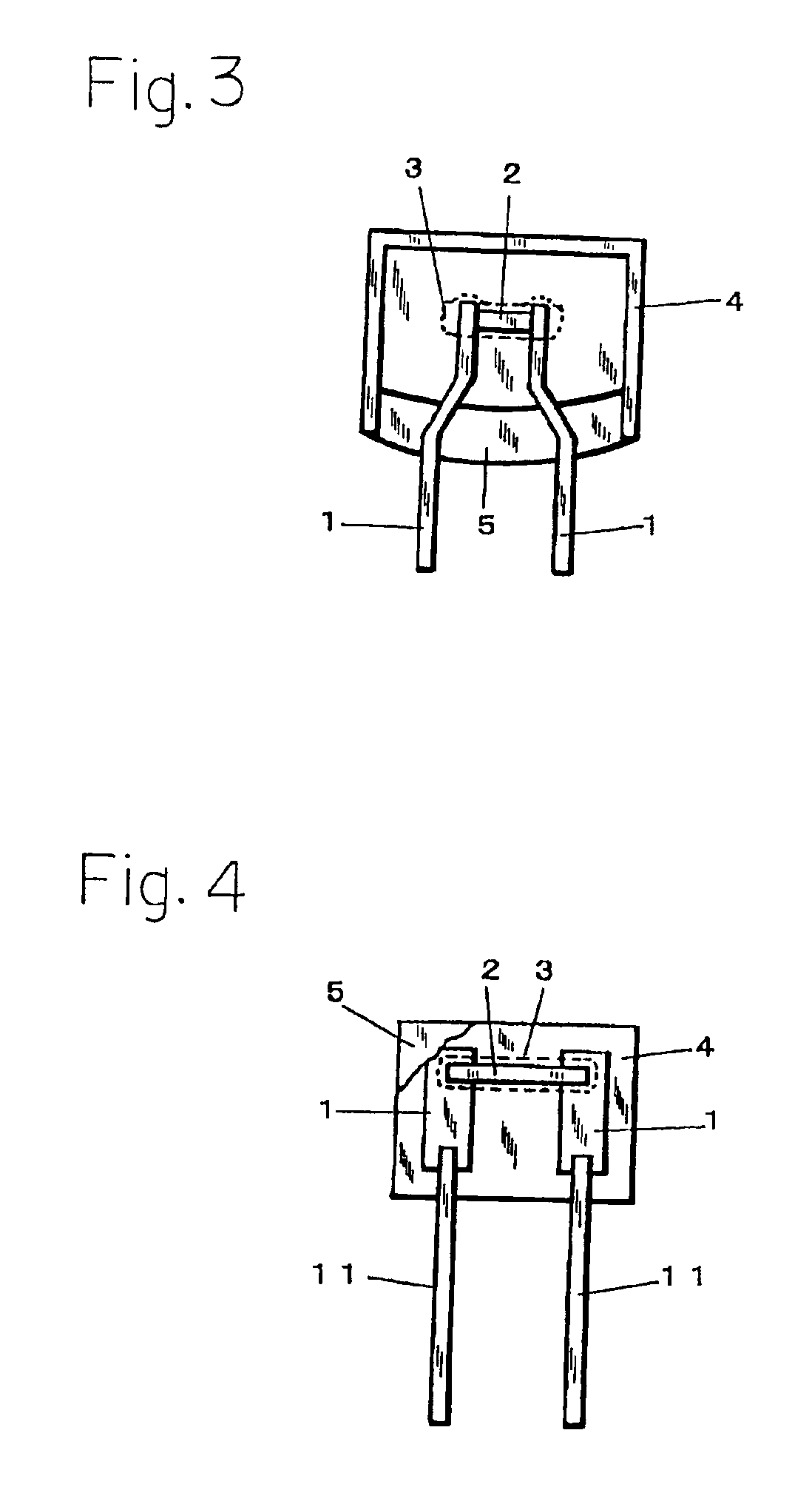
BACKGROUND OF THE INVENTION[0001]1. Field of the Invention[0002]The present invention relates to an alloy type thermal fuse and a wire member for a thermal fuse element, and is useful as a thermoprotector for an electrical appliance or a circuit element.[0003]An alloy type thermal fuse is widely used as a thermo-protector for an electrical appliance or a circuit element, for example, a semiconductor device, a capacitor, or a resistor.[0004]Such an alloy type thermal fuse has a configuration in which an alloy of a predetermined melting point is used as a fuse element, a flux is applied to the fuse element, and the flux-applied fuse element is sealed by an insulator.[0005]The alloy type thermal fuse has the following operation mechanism.[0006]The alloy type thermal fuse is disposed so as to thermally contact an electrical appliance or a circuit element which is to be protected. When the electrical appliance or the circuit element is caused to generate heat by any ab-normality, the fus...

Claims


Application Information

Patent Timeline
Patent Type & Authority Patents(United States)
IPC IPC(8): C22C12/00C22C13/00C22C13/02C22C30/04C22C30/00H01H37/00H01H37/76H01H85/06
CPCC22C12/00C22C13/02C22C30/04H01H37/761H01H2037/768
Inventor IWAMOTO, MIKIIKAWA, NAOTAKASARUWATARI, TOSHIAKITANAKA, YOSHIAKI
Owner UCHIHASHI ESTEC
Learn More