
Turbine shroud segment

a turbine engine and shroud technology, which is applied in the direction of machines/engines, efficient propulsion technologies, liquid fuel engines, etc., can solve the problems of complex installation of the jet cover, increase of etc., and achieve the effect of preventing the temperature elevation of the turbine case, increasing the weight and structure complexity of the turbine engin

Active Publication Date: 2005-11-08
IHI CORP
View PDF11 Cites 39 Cited by
  • Summary
  • Abstract
  • Description
  • Claims
  • Application Information

AI Technical Summary

Benefits of technology

The present invention provides a new design for a shroud segment in a gas turbine engine that effectively suppresses the temperature elevation of the turbine case without the need for a jet cover. The design includes a back plate, a touching member, and a jet shield. The jet shield is integrally formed on the rear end of the back plate and is designed to shield the rear turbine case from a jet of hot combustion gas. The design also includes a front leaf spring and a rear leaf spring that are attached on the outer surface of the shroud segment for insertion into grooves provided for the turbine case. The technical effect of this design is to improve the efficiency and durability of gas turbine engines by reducing the temperature elevation of the turbine case and improving the cooling of the rear turbine case.

Problems solved by technology

However, providing the jet cover causes increase of weight and structure complexity of the turbine engine.
Furthermore, the rear side of the turbine shroud of the last stage has a complex structure so that installation of the jet cover needs elaborated working.

Method used


Image

  • Turbine shroud segment
  • Turbine shroud segment
  • Turbine shroud segment

Examples


Embodiment Construction

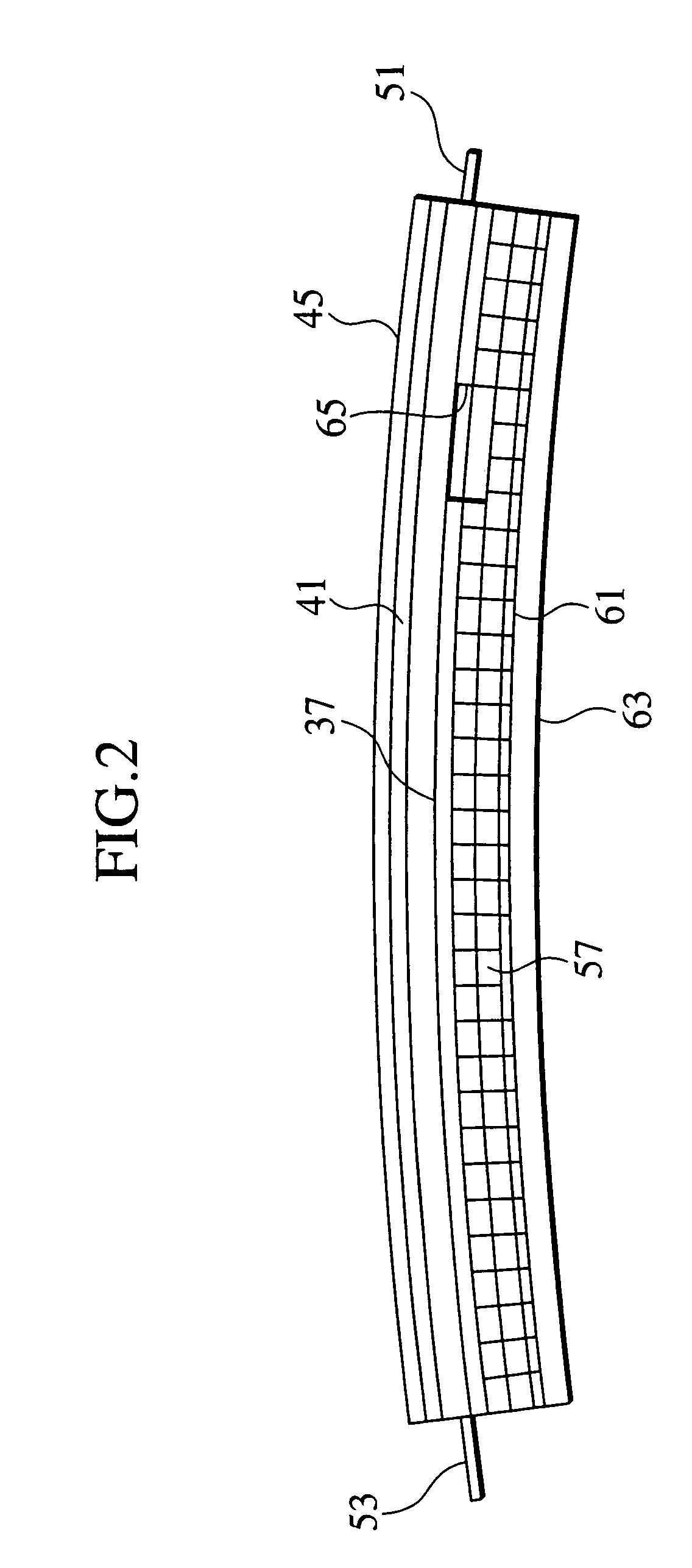
[0020]An embodiment of the present invention will be described hereinafter with reference to FIGS. 1 through 5. Throughout the specification, definition of directions such as front and rear is consistent with directions of elements in practical use. For example, a front end is illustrated on left hand in FIGS. 1 and 5. In and out are defined by near and far from an axis of a turbine engine.

[0021]Referring is now made to FIG. 5. A low-pressure turbine 1 of a turbine engine for an aircraft is provided with a turbine case 3. The turbine case 3 is provided with a main turbine case 5 and a rear turbine case 7 integrally connected with a rear end of the turbine case 5. A front end of the main turbine case 5 is connected with a high-pressure turbine case 9.

[0022]A plurality of turbine nozzles 13, 15 and 17 for rectifying the hot gas are fixed to and housed in the main turbine case 5. Each of the turbine nozzles 13, 15 and 17 is segmented to be plural nozzle segments which are butted end to...


PUM


Abstract

A shroud segment for being incorporated in a gas turbine engine having a turbine case and a rear turbine case connected with a rear end of the turbine case so as to suppress influence of hot combustion gas on the turbine case and the rear turbine case, is provided with a back plate formed in an arc shape and supported by the turbine case, a touching member integrally formed on an inner surface of the back plate for touching with a rotating turbine blade; and a jet shield extended from a rear end of the back plate and slanted radially inward so as to shield the rear turbine case from a jet of the hot combustion gas.

Description

BACKGROUND OF THE INVENTION[0001]1. Field of the Invention[0002]The present invention relates to a gas turbine engine for an aircraft and such and more particularly relates to a shroud segment of a turbine shroud for the gas turbine engine.[0003]2. Description of the Related Art[0004]A turbine of a gas turbine engine for an aircraft and such is provided with plural stages of turbine shrouds for suppressing influence of hot combustion gas on a turbine case. The turbine shrouds are directly exposed to the hot gas and thereby a severe thermal stress might be applied thereto. To avoid an excessive thermal stress, in common, each turbine shroud is segmented. Plural shroud segments are built up to form each turbine shroud.[0005]Each shroud segment is provided with a back plate, as a main body thereof, formed in an arc shape. An outer surface of the back plate is supported by the turbine case. An inner surface of the back plate is integrally provided with a touching member for touching wit...

Claims


Application Information

Patent Timeline
Patent Type & Authority Patents(United States)
IPC IPC(8): F01D11/00F01D25/14F01D25/08F01D25/24F01D11/08F01D11/12F02C7/18F02C7/28
CPCF01D5/225F01D11/005F01D11/08F01D11/122F01D11/127F01D25/145F01D25/246F05D2260/94F05D2260/941Y02T50/671Y02T50/675F05D2220/3215F05D2240/11F05D2230/642Y02T50/60
Inventor TANAKA, AGAMU
Owner IHI CORP
Learn More