
Multi-mode searchlight

a searchlight and multi-mode technology, applied in the field of multi-mode searchlights, can solve the problems of cumbersome and difficult replacement process of failed lamps, flight crews cannot switch from visible to nvis modes, and disadvantages are overcome, so as to achieve easy relamping, reduce heat generation, and improve light output

Inactive Publication Date: 2005-11-08
HONEYWELL INT INC
View PDF18 Cites 39 Cited by
  • Summary
  • Abstract
  • Description
  • Claims
  • Application Information

AI Technical Summary

Benefits of technology

The present invention is a multi-mode lighthead that solves problems associated with previous lightheads, such as being difficult to re-lamp, having limited visibility, and generating too much heat. The lighthead has an imaging module that captures an image from the front of the housing and a reflective device that emits light from the front of the housing. The lighthead also has a high power infrared diode and a visible light source, providing better visibility and infrared imaging. The lighthead can be easily attached to a searchlight and controlled by a positioning and control system. The invention also includes a searchlight controller for tracking an absolute location of a target. Overall, the invention improves the visibility and safety of flight crews during operation.

Problems solved by technology

A disadvantage of early NVIS-compatible lighting systems was that the flight crew could not switch from visible to NVIS modes during a mission, since the infrared filters were required to be installed and removed while the aircraft was on the ground.
This disadvantage was overcome by prior dual mode lightheads containing both visible and infrared lighting elements.
While prior dual mode lightheads offer significant advantages over early manually-installed filters, they suffer from several disadvantages.
First, replacement of failed lamps is a cumbersome and difficult process owing to the segmented lens and filter assembly which must be removed and then re-sealed each time a lamp is replaced.
This repair frequently causes damage to the reflectors, thereby reducing the optical efficiency of the lighthead.
Further, prior dual mode lightheads utilize visible light sources coupled with infrared filters to produce the infrared light, generating high temperatures within the lighthead that can limit the life of the light elements, lenses, and sealing materials.
However, this system requires a relatively complex comparator to permit the synchronized operation of the separate devices.

Method used


Image

  • Multi-mode searchlight
  • Multi-mode searchlight
  • Multi-mode searchlight

Examples


Embodiment Construction

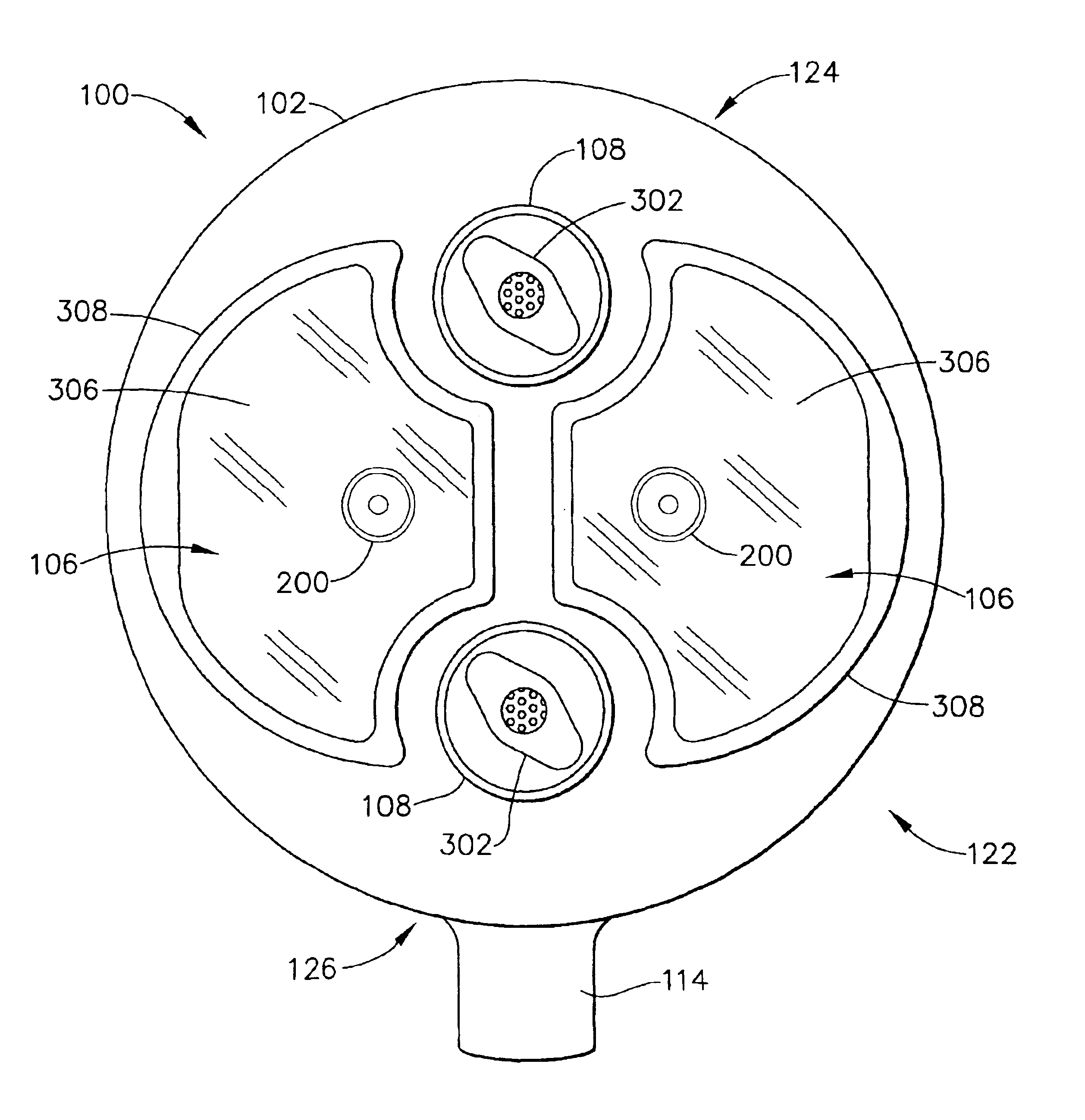
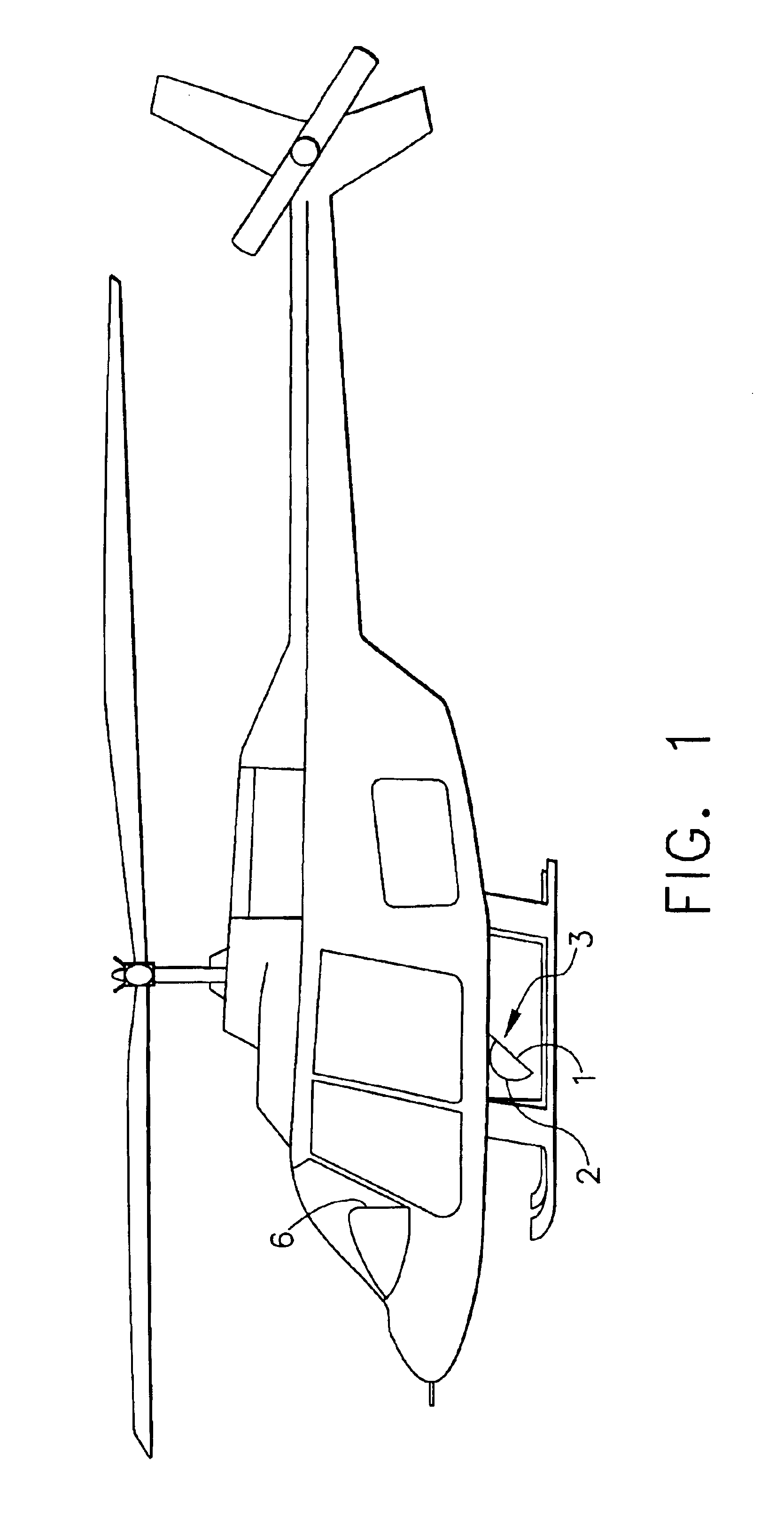
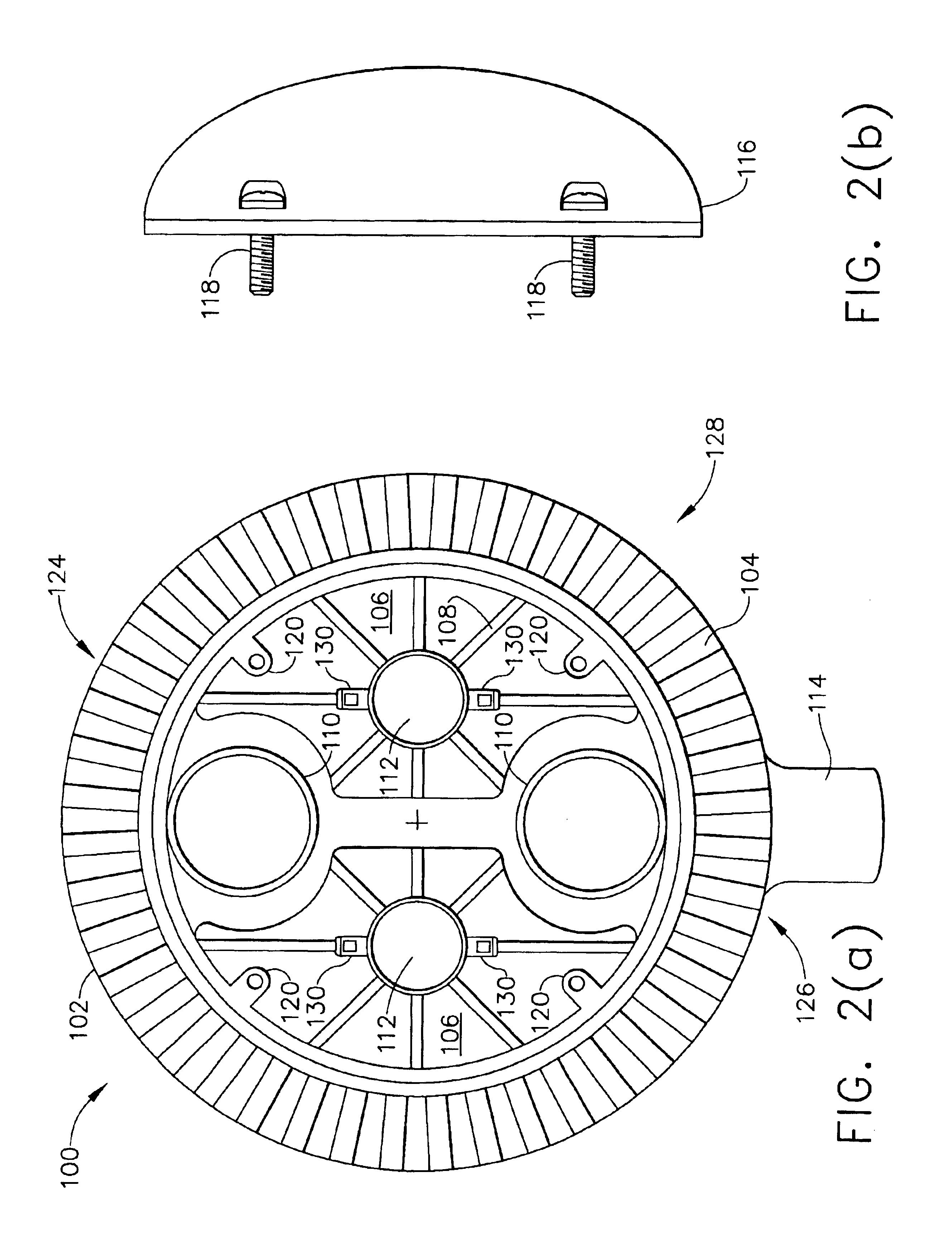
[0043]The present invention will now be described in detail with reference to the accompanying drawings. FIG. 1 is a side view of a helicopter equipped with a multimode searchlight according to the present invention. FIG. 2(a) is a rear view of a multi-mode searchlight according to an embodiment of the present invention. FIG. 2(b) is a side view of a rear cover for the multi-mode searchlight shown in FIG. 2(a). FIG. 3 is a perspective view of a visible light source for a multi-mode searchlight of the present invention. FIG. 4 is a front view of a multi-mode searchlight according to an embodiment of the present invention. FIG. 5 is a schematic view of an exemplary electrical circuit of a multi-mode searchlight according to an embodiment of the present invention.

[0044]The present inventors have analyzed the needs of the background art and identified several shortcomings associated with the systems of the background art. For example, the present invention incorporates a modular design ...


PUM


Abstract

A multi-mode visible and infrared lighthead (100) for use as a landing light or searchlight. The multi-mode lighthead incorporates a modular design wherein at least one visible light source (200) and at least one infrared diode (302) are mounted into the rear sector (128) of a housing (102). Visible or infrared light is emitted out of the front sector (122) of the housing (102). Lenses (308) are installed onto the front sector (122) of the housing (102) and sealed to protect the interior of the lighthead (100) from the elements. Alternatively, and in combination, an imaging module (1), and infrared laser (400) and / or a fixed-position searchlight with rangefinder and positioning capability is provided in the multi-mode lighthead(100).

Description

CROSS-REFERENCES TO RELATED APPLICATIONS[0001]This nonprovisional application claims the benefit of U.S. Provisional Application No. 60 / 332,793, filed on Nov. 6, 2001, the entirety of which is herein incorporated by reference.TECHNICAL FIELD AND INDUSTRIAL APPLICABILITY OF THE INVENTION[0002]The present invention is generally directed to a multi-mode searchlight, and more particularly to a multi-mode searchlight providing infrared, conventional, and / or other miscellaneous visual aids for an operator of a helicopter. Specifically, the present invention relates to a multi-mode visible and infrared lighthead for use with aircraft landing lights and searchlights, and for use with other vehicles and systems.BACKGROUND OF THE INVENTION[0003]The following discussion of the background art is a result of the present inventors analysis of the systems and features of searchlight technology of the background art. The present invention relates to limitations on a flight crew's ability to see are...

Claims


Application Information

Patent Timeline
Patent Type & Authority Patents(United States)
IPC IPC(8): B64D47/02B64D47/00B64D47/08B64D47/04
CPCB64D47/04B64D47/08B64C2027/8236Y10S362/80B64D2203/00
Inventor HAMILTON, SCOTT E.GIFFEN, CRAIG E.MACHI, NICOLO F.MANGUM, SCOTT R.MUBASLAT, SAED S.ROUDESKI, CHARLES A.
Owner HONEYWELL INT INC
Learn More