
Fiber optic sight for firearms with nighttime capabilities

a fiber optic sight and nighttime capability technology, applied in the field of fiber optic sight with nighttime capabilities, to achieve the effect of increasing the amount of light directed toward the shooter's eyes and sufficient illumination capabilities of the fiber optic sigh

Inactive Publication Date: 2009-12-08
WILSONS GUN SHOP
View PDF9 Cites 78 Cited by
  • Summary
  • Abstract
  • Description
  • Claims
  • Application Information

AI Technical Summary

Benefits of technology

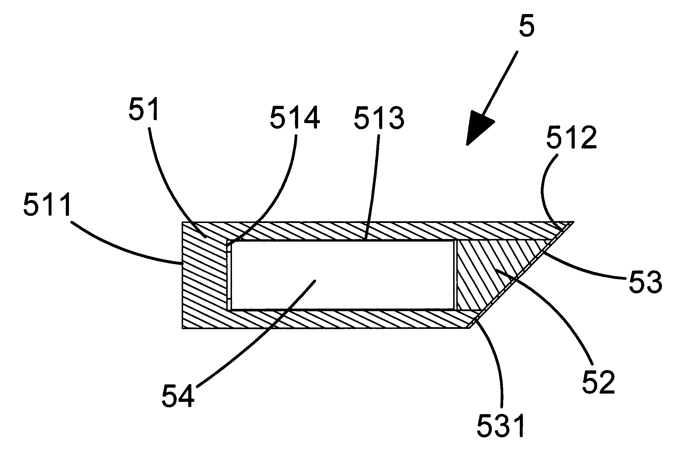
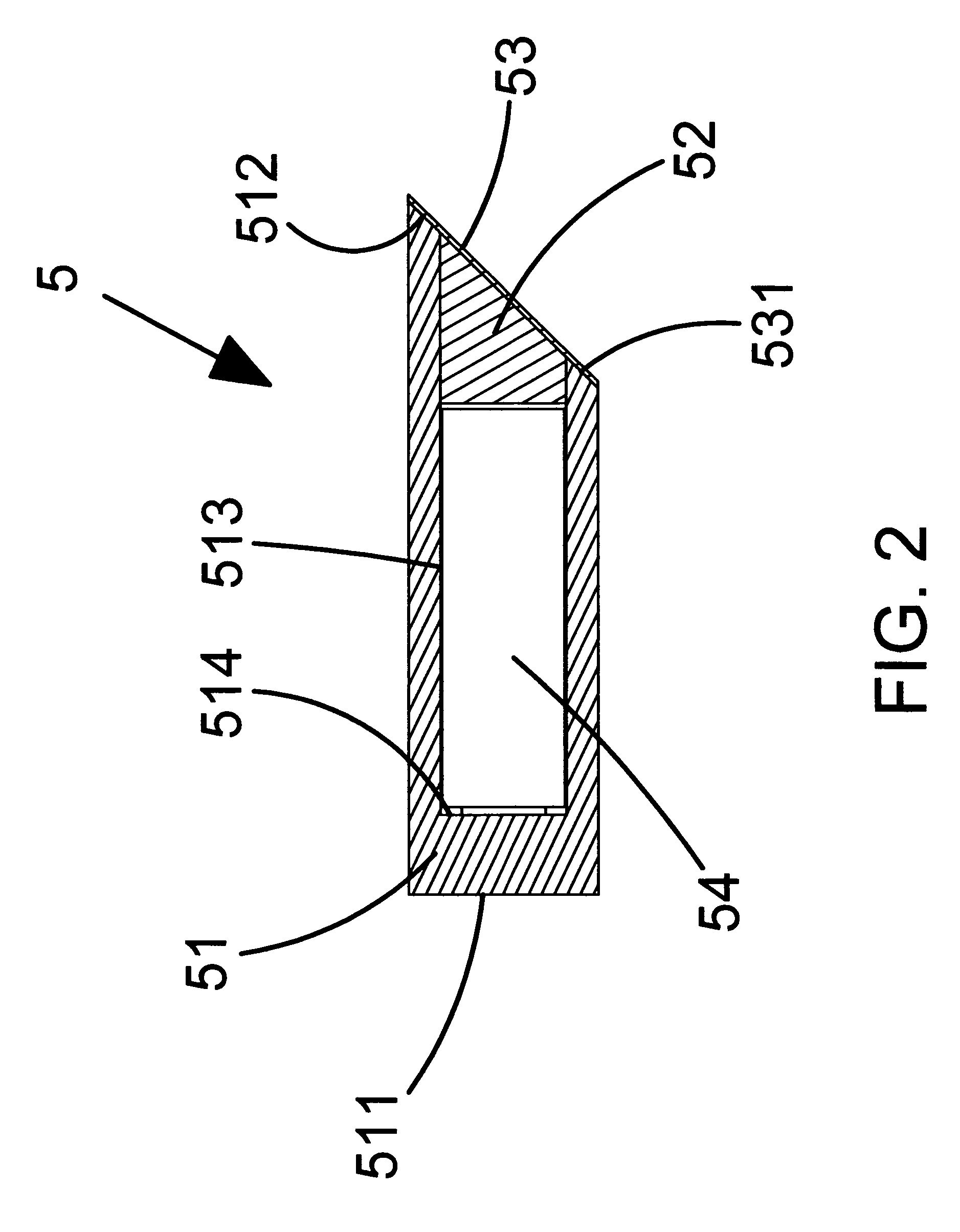
[0007]A further object is to provide the shooter with a sighting system that results in increased illumination being directed towards the shooter's eyes during the day. The sight achieves this through the use of an angled cut at the forward end of the fiber optic rod. The cavity for the tritium insert enters the rod from the angled surface so after the tritium insert is epoxied into place, a plug of the same fiber rod is inserted and also epoxied into place utilizing an optically clear epoxy. The angled surface is positioned in a sight base which secures the rod with the angled surface on the bottom of the rod and exposes the top portion of the rod to external ambient light. The angled cut can be polished and acts as a mirror surface that effectively redirects the light striking the exposed surface of the rod, which travels thru the rod then reflects off the polished angled surface back along the long axis of the fiber rod toward the shooters eyes. The tritium insert does not transmit light shined unto its distal end since it is normally sealed with an optically opaque material in order to increase light output from the viewing lens during nighttime operations. Thus during the day the shooter will see a bright ring of light which surrounds the darker tritium insert. Additionally, a reflective coating or mirrored material can be applied directly to, mated or bonded to the polished angled surface to improve the reflectivity of the polished angled surface and further enhance the redirection of light striking the exposed portion of the fiber rod back along the long axis of the fiber toward the shooters eyes. The angled surface can be hidden from view forward of the sight by positioning the rod below the top surface of the holder. Adding a reflective coating or mirrored material to the angled surface also blocks any light from being reflected forward of the angled surface which could expose the shooters location.
[0020]A fourth unique improvement is the ability to adequately protect the fiber optic rod and its enclosed tritium vial from damage due to external shock by allowing the short optical fiber assembly to be set into a pocket within the sight which provides side and bottom protection for the fiber. Even with the relatively small amount of surface being exposed to illumination from ambient light, the amount of light directed toward the shooters eyes is still increased.

Problems solved by technology

There are many fiber optic sights available which utilize tritium inserts for illumination during nighttime operations but there are a number of problems with such sights.
While having the tritium insert coplanar with the front face of the fiber optic rod would result in a 0.050 inch shorter package length, in so doing the transition from day to night would not result in as good of blending of the twilight glow with that of glow from the tritium insert that occurs within a single fiber.

Method used


Image

  • Fiber optic sight for firearms with nighttime capabilities
  • Fiber optic sight for firearms with nighttime capabilities
  • Fiber optic sight for firearms with nighttime capabilities

Examples


Embodiment Construction

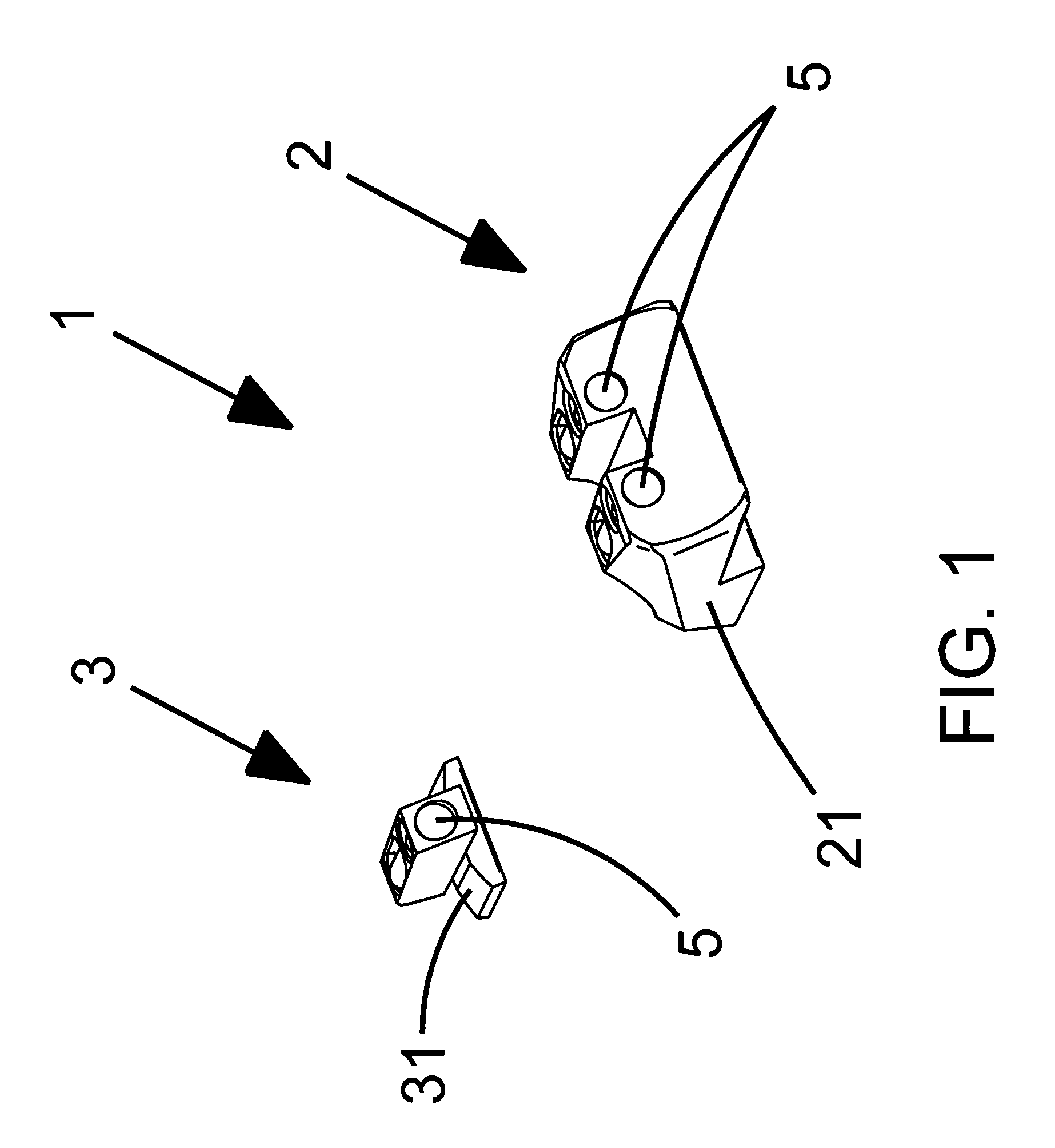
[0025]Referring in detail to FIG. 1 of the drawings, the fiber optic sight set with nighttime sighting capability 1 consists of a fiber optic rear sight assembly with nighttime sighting capability 2 and a fiber optic front sight assembly with nighttime sighting capability 3. The fiber optic rear sight assembly with nighttime sighting capability 2 contains sight base 21 and two fiber optic rod assemblies 5. The fiber optic front sight assembly with nighttime sighting capability 3 contains front sight base 31 and one fiber optic rod assembly. All three of the fiber optic rod assemblies 5 are bonded to rear sight base 21 and front sight base 31 using an optically clear adhesive (not shown).

[0026]Referring in detail to FIG. 2 of the drawings, the fiber optic rod assembly 5 has a fiber optic rod 51, a front plug 52, a reflector 53 and tritium insert 54 all of which are bonded into a single unit utilizing an optically clear adhesive (not shown). Fiber optic rod 51 has a rear face 511, a s...


PUM


Abstract

New and unique improvements of prior known fiber optic sights for firearms with day and night time capabilities are disclosed that comprise (A) a sight base, (B) a fiber optic rod mounted in said base having an angle cut at the distal end which is positioned on the underside of the rod, and (C) an artificial light insert that is positioned in a cavity in the fiber optic rod. The cavity is sealed with a fiber optic rod plug and epoxied using an optically clear epoxy. The sight provides increased light output, co-located day and night sight views with increased illumination during the day, and uses a low power tritium insert for night time use. At night the sight achieves a transition from a bright ring during the day to a small central dot at night while maintaining the same color light for both.

Description

BACKGROUND OF THE INVENTION[0001]1. Field of the Invention[0002]This application relates broadly to a fiber optic sight for firearms. More particularly, it concerns an improved form of a fiber optic sight with nighttime capabilities for use with firearms, including handguns and long arms.[0003]2. Description of the Prior Art[0004]Co-pending U.S. patent application Ser. No. 11 / 899,069 filed Sep. 5, 2007, “Fiber Optic Sight for Firearms”, is hereinto incorporated as a reference for this current application. There are many fiber optic sights available which utilize tritium inserts for illumination during nighttime operations but there are a number of problems with such sights. Generally there have been four methods of dealing with the light emitted from a tritium night insert. The first is to put the tritium insert at the distal end of the fiber in which case the light emitted from the tritium vial must travel thru the full length of the fiber. An example of this method is disclosed in...

Claims


Application Information

Patent Timeline
IPC IPC(8): F41G1/32
CPCF41G1/345
Inventor OLSON, DOUGLAS D.
Owner WILSONS GUN SHOP
Learn More