
Variable force energy dissipater and decelerator

a technology of energy dissipation and variable force, which is applied in the direction of spring/damper, elastic damper, way, etc., can solve the problems of ineffective management and control of harmful deceleration forces, inherently inefficient extraction of deformation energy, and inability to effectively handle a wide range of impact masses, velocities or kinetic energies, so as to minimize injury to occupants or excessive damage to equipment and vehicles, efficient and cost-effective management, and the effect of excessiv

Inactive Publication Date: 2005-11-08
WORCESTER POLYTECHNIC INSTITUTE
View PDF52 Cites 53 Cited by
  • Summary
  • Abstract
  • Description
  • Claims
  • Application Information

AI Technical Summary

Benefits of technology

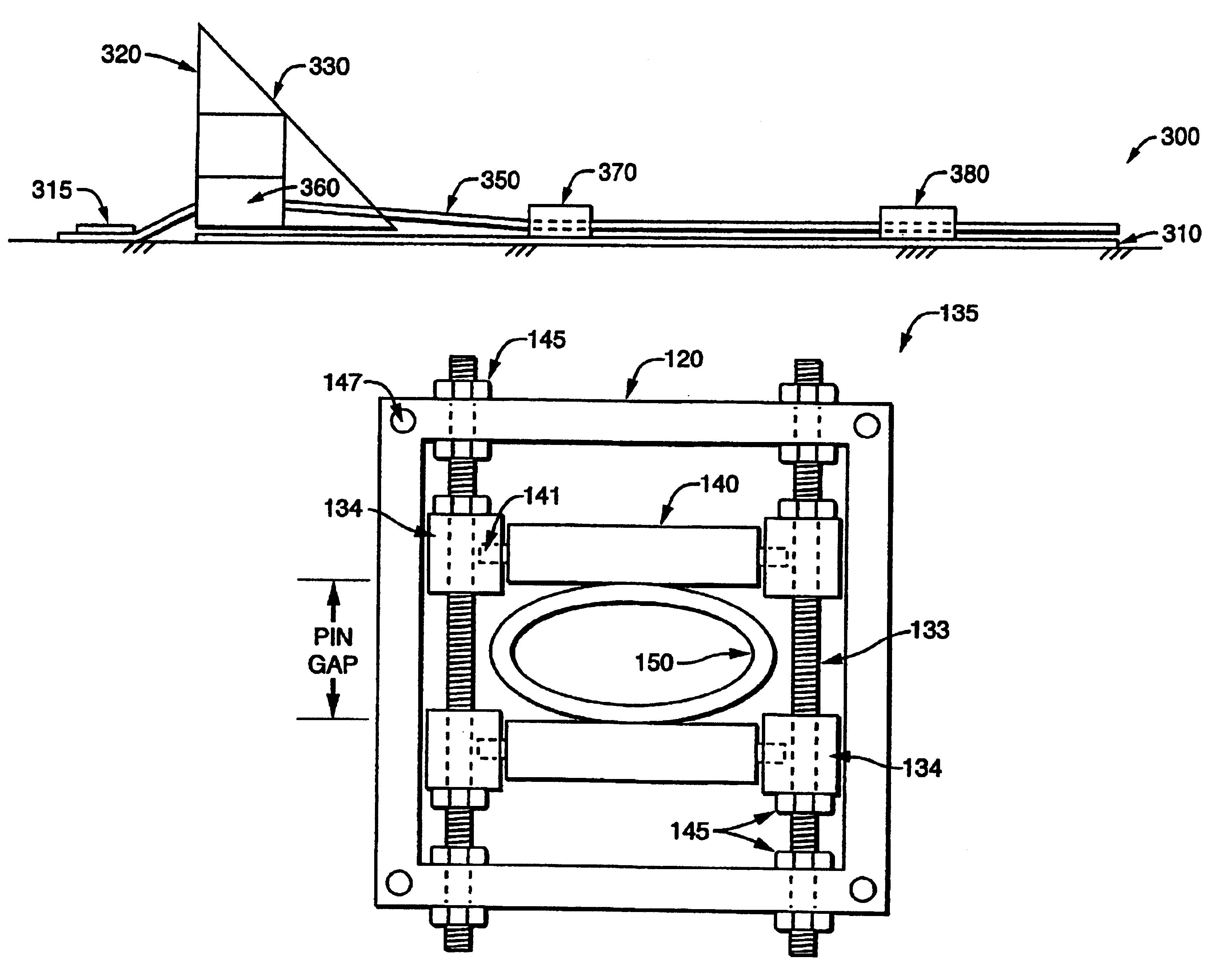
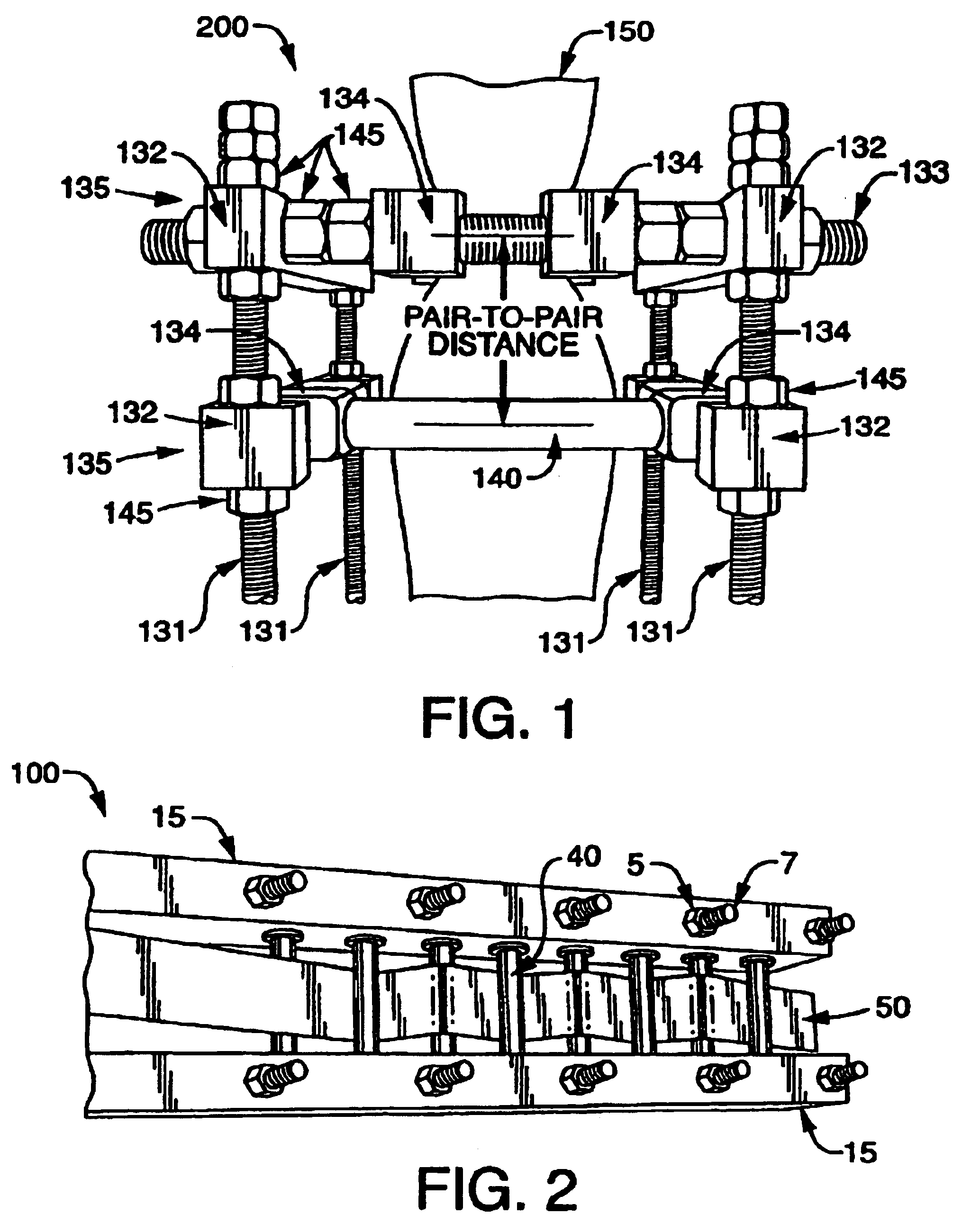
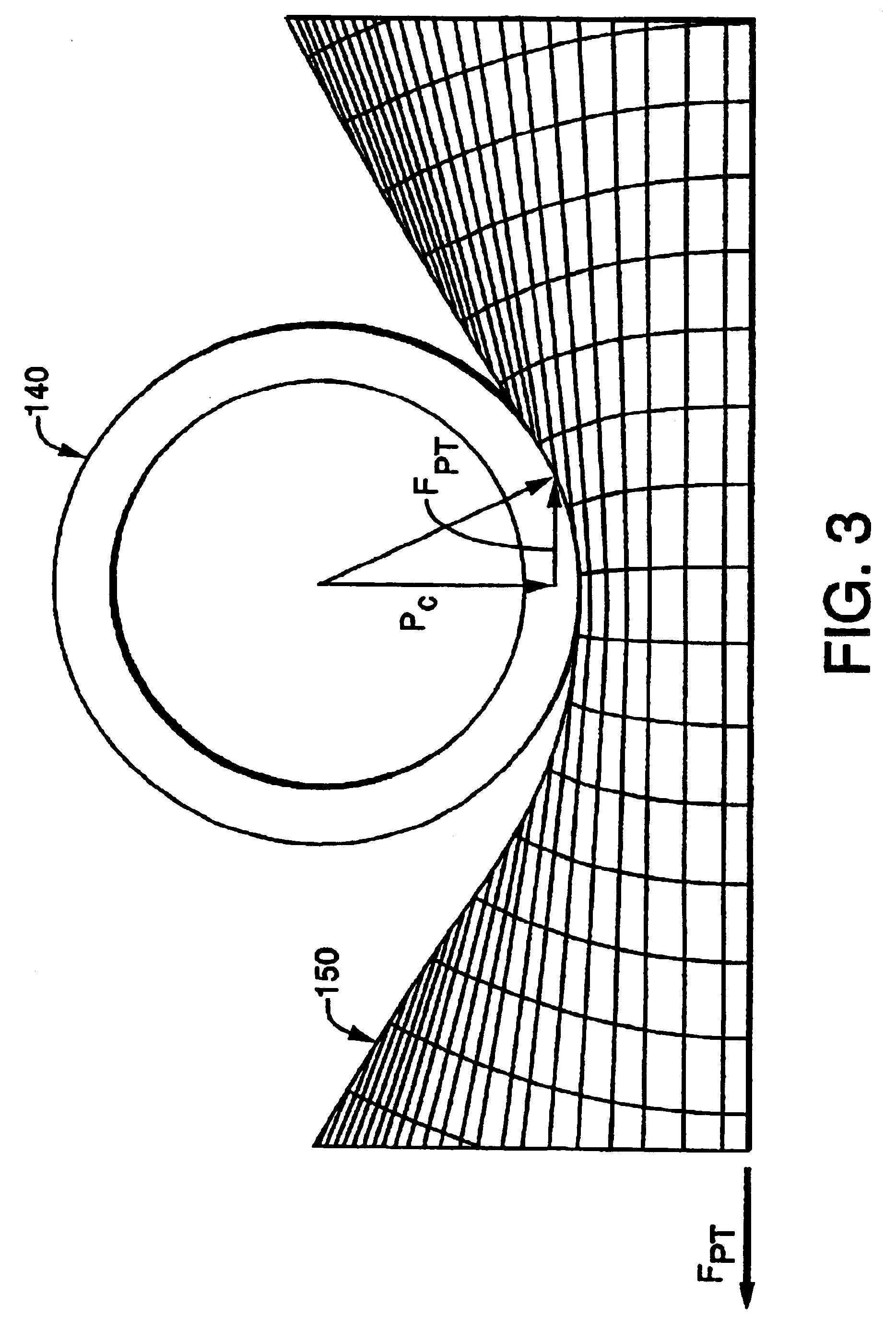
[0015]The energy attenuator and decelerator of the present invention relies on the principle that a broad range of kinetic energies produced by moving objects can be safely absorbed on impact by employing variable deceleration forces through the repeated, successive, transient deformation of inelastic or viscoelastic deformable members at stresses up to and beyond their elastic limit but typically below their failure point.

Problems solved by technology

As such, due to designed limitations in energy absorption capacity and deceleration force, these prior art devices are typically unsuitable for handling a wide range of impact masses, velocities or kinetic energies.
Furthermore, while these prior art devices may effectively dissipate the kinetic energies for which they are designed, due to their typical constant force limitations, they generally do not provide for effective management and control of harmful deceleration forces produced by varying force-time profiles.
Additionally, since these prior art devices typically rely on kinetic energy dissipation through the irreversible plastic deformation of deforming members at stresses well above their proportional limit and yield point, such devices are inherently inefficient in extracting deformation energy from materials since, following initial deformation of the members, subsequent deformation and energy dissipation is minimal since the initial deformation is typically irreversible.
Furthermore, these devices have associated high maintenance costs since, deforming members must be replaced after use due to irreversible deformation.
In subsequent testing, Ray, et al., evaluated the performance of conventional highway crash guardrail terminals in side impact collisions and found that existing devices failed to protect vehicle occupants from significant intrusion of guardrail terminals into passenger compartments which is a major source of fatal injuries in side impact collisions [see M. H. Ray, et al., Report Nos.
Based on a review of recent studies of side impact collisions and resultant occupant injuries, Ray, et al. concluded that conventional crash cushions and guardrails are primarily designed for dissipating vehicle kinetic energy in head-on collisions and are not adequately designed to minimize occupant injury during side-impact collisions with their associated acceleration profiles [see M. H. Ray, “Side Impact Test and Evaluation Procedures”, Federal High Administration Report No.
In addition, Ray, et al. demonstrated that decelerations produced by current generation crash cushions are suitable for either small 820 kg passenger cars or large 2000 kg pickup trucks but are not appropriate for the majority of 1450 kg mid-sized vehicles.

Method used


Image

  • Variable force energy dissipater and decelerator
  • Variable force energy dissipater and decelerator
  • Variable force energy dissipater and decelerator

Examples


example 1

Pull-Through Strap Dissipater

[0176]Quasi-static testing of various pull-through strap energy dissipater configurations was performed with an 1800 kN laboratory load tester. Due to equipment limitations, measurements were made at low strain rates, typically less than 20″ / min. For these tests, hot-rolled 50.8 mm wide A36 steel straps were evaluated as deforming elements. Both 3.2 mm and 4.8 mm thick straps were tested. Both 12.7 mm and 19.1 mm pin diameters were evaluated. Four, five, six and eight pin dissipater module performance was compared with constant pin set spacing of 50.8 mm. To avoid unsystematic variation in results due to uncontrolled friction forces, lubricated rolling pins were used for all tests. Both unstrained and strained steel strap samples were tested in order to evaluate work hardening effects. Pull-through force FPT, energy dissipation and elongation were measure for all samples. Pull-through force and energy dissipation data for various pull-through strap dissi...

example 2

Pull-Through Tube Dissipater

[0179]Pull-through force and energy dissipation of single pin pair and two pin pair pull-through tube dissipater modules was measured with the drop tower test method described above. The influence of pin gap spacing on dissipater performance was evaluated for both module types and the influence of pin pair spacing was evaluated for two pin pair modules. Pin gap spacing of 30 mm, 35 mm and 40 mm and pin pair spacing of 100, 150 and 200 mm were studied. For both dissipater types, impact masses of 80.5 kg, 107 kg and 128 kg were employed, representing approximate impact velocities of 2.58 m / s, 3.94 m / s and 5.01 m / s. In all cases, 89 mm HDPE tubing was utilized as deforming member elements.

[0180]Test results for single pin pair modules are provided in Table 7 and plotted in FIG. 19 which shows the dissipated energy as a function of pin pair gap spacing and dissipater module displacement. As FIG. 19 demonstrates, dissipation energy increase with increasing dis...

example 3

Pull-Through Tube Energy Dissipater Crash Cushion

[0184]Using the criteria for vehicle crash cushion design performance discussed above, a variable force, pull-through tube energy dissipater was designed to achieve the requisite acceleration (deceleration) profile and thereby satisfy the three design requirements for minimizing occupant injury in a head-on collision: a) a maximum occupant impact velocity (OIV); b) a maximum g-force for occupant ride-down acceleration (ORA); and c) adequate energy dissipation to stop a 2000 kg pickup truck traveling at 100 km / hr.

[0185]As noted above, the pull-through force necessary in the first stage to meet the small car OIV requirement was shown to be 55 kN. Thus, the first task for crash cushion design was to select a configuration which will result in a force in the range for the low-force end of the cushion. In FIG. 13 a pull-through force FPT of 10 kN is obtained with a diameter-thickness ratio of approximately six for a clamping ratio of 0.775...


PUM


Abstract

Tunable pull-through energy attenuator and decelerator devices is disclosed which provide for variable force-time profiles, deceleration and kinetic energy attenuation of moving objects so as to prevent damage or injury to impacting objects, vehicles or persons. The device employs either consumable inelastic or reusable, viscoelastic deforming elements, such as tubes, rods, plates or strips, which absorb substantial amounts of energy through repeated inelastic or viscoelastic deformation when the deforming element is pulled-through a tunable array of rigid pins having a variety of configurations and settings. The disclosed devices provide for variable force-time profiles which control the cumulative deformation and thereby the amount of energy absorbed and rate of deceleration of impacting objects. The device may be readily adapted and deployed as highway vehicle guardrails, road barriers or crash cushions for frontal and side impacts and as load attenuators for crash-resistant aircraft seats, spacecraft landing pods, crash-resistant aircraft landing gear, aircraft and vehicle passenger restraint harnesses, cargo tie-downs, vehicle bumpers and collapsible vehicle steering columns.

Description

CROSS-REFERENCES[0001]This application claims the benefit under 35 U.S.C. 119(e) of U.S. provisional patent application U.S. Ser. No. 60 / 384,903 filed on Jun. 1, 2002 which is incorporated herein by this reference.FIELD OF THE INVENTION[0002]This invention relates generally to energy attenuator devices and methods for deceleration of moving objects. More particularly, this invention relates to tunable, variable force, pull-through energy attenuators and decelerators which provide for controlled deceleration so as to prevent damage or injury to moving objects, vehicles or persons.BACKGROUND OF THE INVENTION[0003]Numerous applications of kinetic energy absorbers are known in the art. Examples include, but are not limited to, load attenuators for crash-resistant aircraft seats, spacecraft landing pods, crash-resistant aircraft landing gear, aircraft and vehicle passenger restraint harnesses, cargo tie-downs, automotive bumpers, collapsible vehicle steering columns and highway vehicle c...

Claims


Application Information

Patent Timeline
IPC IPC(8): E01F9/018E01F9/011E01F13/00F16F7/12F02D
CPCF16F7/123E01F15/146
Inventor RAY, MALCOLM H.PLAXICO, CHUCK A.
Owner WORCESTER POLYTECHNIC INSTITUTE
Learn More