
Underwater maneuvering device

a maneuvering device and underwater technology, applied in underwater equipment, special-purpose vessels, vessel construction, etc., can solve the problems of user's use of both hands for proper control, the twin hand control requires substantial coordination and skill for proper use, and the relative complexity and cost of manufacture, etc., to achieve convenient storage and transportation, quick disassembly, and substantial arm or body strength

Inactive Publication Date: 2005-11-08
TUNKS TIMOTHY E
View PDF4 Cites 5 Cited by
  • Summary
  • Abstract
  • Description
  • Claims
  • Application Information

AI Technical Summary

Benefits of technology

[0008]Therefore, although the present invention may be “flown” by a user with both hands, it also can be controlled with a one handed grip of the dive tether and the horizontal tether. Since the tethers normally trail behind the device to a location behind the rigid bar, one handed capability greatly enhances the user's euphoric sense of control, the user's field of vision, as well as the efficiency of the dive plane and fin, for then they are well ahead of any disturbed water flow caused by the user's turbulence. One handed operation also allows underwater photography with simple cameras and nostril pinching for the purpose of middle ear pressure equalization.
[0015]It is a final object of the present invention to provide a fun and empowering experience to the user because of the ease and naturalness of control, as well as greatly increasing a user's range of motion through the water.

Problems solved by technology

While the Scott device provides substantial vertical directional control for a user, it has many moving parts, and appears to be relatively complex and expensive to manufacture.
Its twin hand controls require substantial coordination and skill for proper use.
Furthermore, the twin non-centered controls require the user to use both hands for proper control.
The user lacks a free hand for such activities such as scallop harvesting or photography.
The Scott device also lacks the ability to provide substantial horizontal directional control.
U.S. Pat. No. 5,482,485 by Ball discloses an underwater maneuvering device that is unnecessarily large and bulky.
The base member is much larger than is required for all but the most buoyant of divers, and there are two vertical fins adding to the complexity of its manufacture.
It provides only limited one hand maneuverability, which impedes nostril pinching for middle ear pressure equalization as well as other activities discussed above.

Method used


Image

  • Underwater maneuvering device
  • Underwater maneuvering device
  • Underwater maneuvering device

Examples


embodiment 30

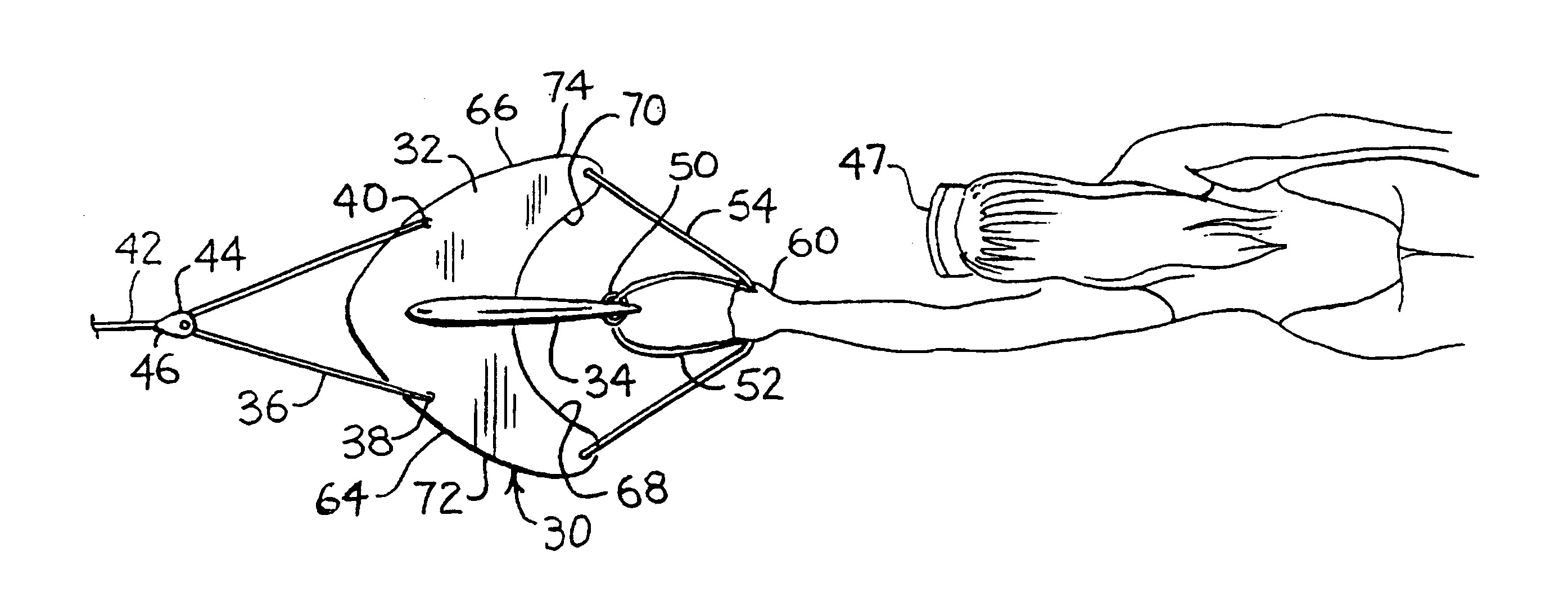
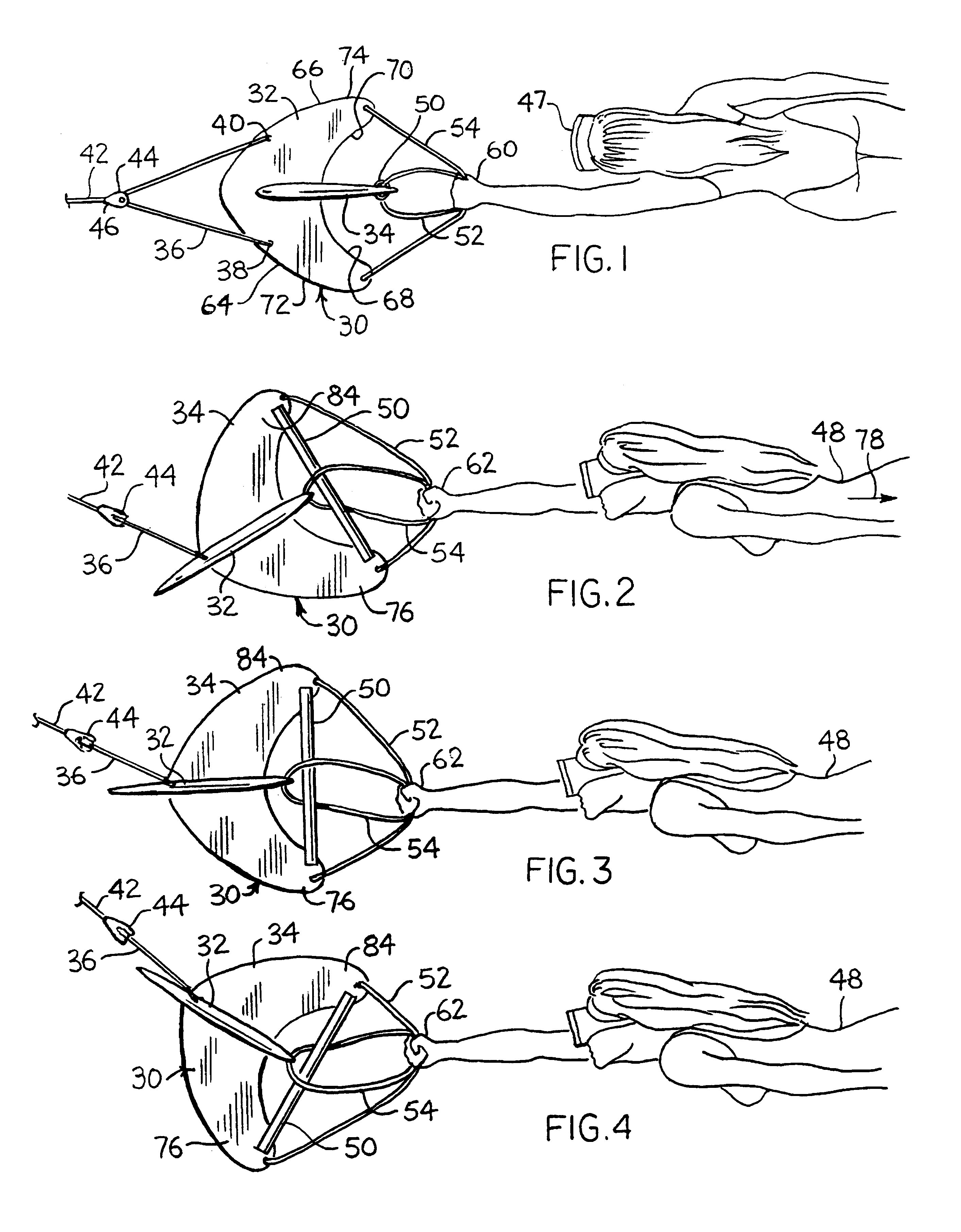
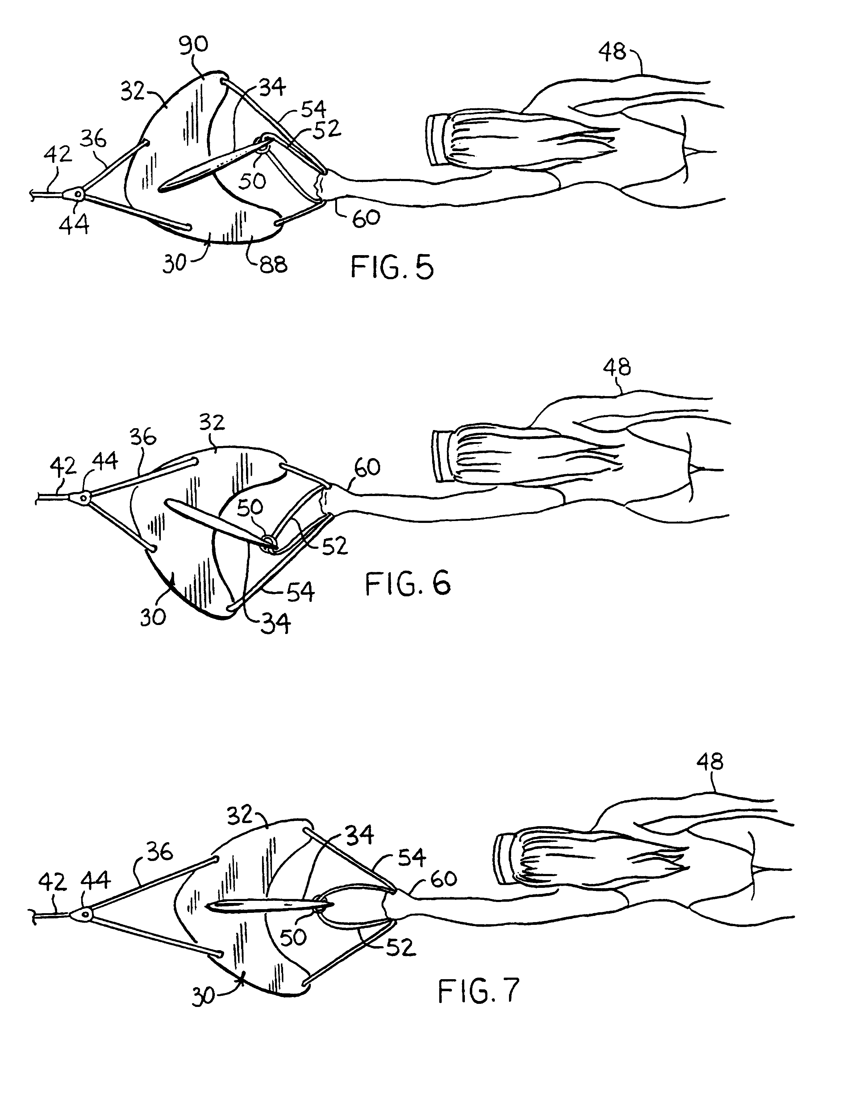
[0040]Referring to the drawings, more particularly by reference numbers, number 30 in FIG. 1 refers to a towed, underwater maneuvering device. The device 30, as shown, includes a dive plane 32, a fin 34 connected at right angles thereto, and a bridle 36 connected, in embodiment 30, at spaced locations 38 and 40 on the dive plane 32. The bridle 36 is attached to a tow line 42 preferably by some sort of low friction means, such as the single sheave pulley 44 shown. Even though the pulley 44 can include a swivel 46, if the tow line 42 is braided line rather than twisted rope, swivel 46 is not really needed unless the device is used acrobatically, including a series of rolls in the same direction, or the tow line 42 is deployed with an initial twist. Twisted line is not recommended as such tends to unwind with an increasing load which may cause tangles when abruptly unloaded even though a swivel 46 is present.

[0041]The tow line 42 is used to pull the device 30 through the water at relat...

embodiment 202

[0054]FIG. 18 shows the fin member 200 of a molded take apart embodiment 202, as shown the fin member 200 includes a slot 204 extending rearwardly from its leading edges 206 and 208 and the rigid bar 210 is also part of the unitary construction. A vertical tether 212 is connected at the opposite ends of the rigid bar 210. Note that in device 202, the bridle 214 with its pulley 216, is attached to the fin member 200, rather than the dive plane member 220 shown in FIG. 19. Since, in most instances, the primary forces applied to the device 202 by a user are through the rigid bar 210 or the vertical tether 212, this keeps all of the stresses within the fin member 200, which if hollow rotomolded, can be filled with foam 222 and weighted with shot 224 in its rigid bar 210 for strength and rigidity, and to produce the desired tendency to return to the surface under tow. The dive plane member 220 includes a slot 226 which extends from its trailing edges 228 and 230, a pair of channels 232 e...


PUM


Abstract

An underwater maneuvering device is disclosed. It utilizes a horizontal planar member, a perpendicularly disposed fin member, hand grip portions, and a towing bridle, pulley and towline assembly that permit the device to freely change its angular alignment to the towline for diving, turning and surfacing maneuvers. The arrangement of the members and hand grip portions permit gripping thereof by the diver so that the drag forces of the diver input the forces needed to control the device, requiring little or no additional effort on the part of the diver. The device may be constructed to disassemble for easy transport and storage.

Description

[0001]This application is a 371 of PCT / US00 / 25887, filed Sep. 19, 2000, which claims the benefit of provisional application 60 / 154,773 filed Sep. 20, 1999.TECHNICAL FIELD[0002]The present invention generally relates to an aquatic maneuvering device, more specifically to an improved maneuvering device for use on and under the water whenever the user is being propelled through the water by auxiliary means such as a tow boat or jet ski, mechanical cable, or by the propulsion effects of water current.BACKGROUND ART[0003]Water-borne activities are extremely popular. Such activities take place in rivers, lakes, oceans and just about anywhere a suitable body of water can be found. These activities include those performed both under and above the water surface. People spend a lot of time engaged in underwater activities. These activities include underwater survey, scallop and clam searching, spear fishing, sand dollar harvesting, sightseeing, photography, acrobatic play, etc. Typically, a p...

Claims


Application Information

Patent Timeline
Patent Type & Authority Patents(United States)
IPC IPC(8): B63C11/46B63G8/42B63H25/10
CPCB63C11/46B63H25/10B63C2011/028
Inventor TUNKS, TIMOTHY E.
Owner TUNKS TIMOTHY E
Learn More