
Aluminum automotive drive shaft

a technology for automotive driveshafts and aluminum components, which is applied in the field of aluminum automotive drive shafts, can solve the problems of dc cast ingots or billet materials having a higher total conversion cost associated, affecting the efficiency of aluminum components, and reducing the benefit of aluminum components' weight savings

Inactive Publication Date: 2005-11-01
COMMONWEALTH INDS
View PDF46 Cites 35 Cited by
  • Summary
  • Abstract
  • Description
  • Claims
  • Application Information

AI Technical Summary

Benefits of technology

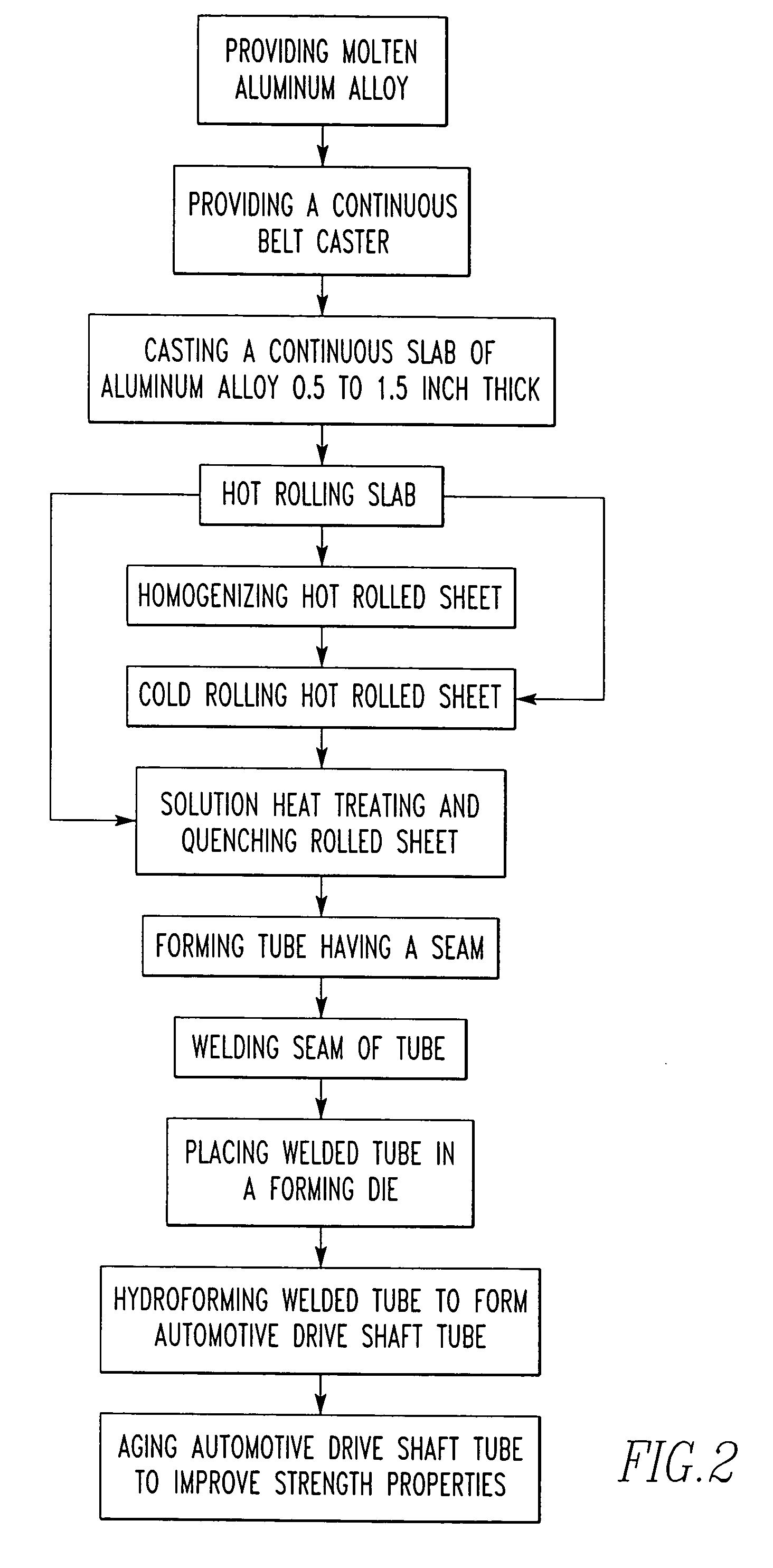
[0035]In accordance with these objects there is provided a process for the production of an aluminum automotive drive shaft from a heat treatable aluminum alloy using a continuous caster to cast the alloy into a slab wherein in said production an aluminum drive shaft tube member is joined to end members to form the drive shaft. The aluminum drive shaft tube member is made by the method comprising providing a molten aluminum alloy consisting essentially of 0.2 to 0.8 wt. % Si, 0.05 to 0.4 wt. % Cu, 0.45 to 1.2 wt. % Mg, 0.04 to 0.35 wt. % Cr, 0.7 wt. % max. Fe, 0.15 wt. % max. Mn, 0.25 wt. % max. Zn, 0.15 wt. % max. Ti, the remainder aluminum, incidental elements and impurities, and providing a continuous caster for continuously casting the molten aluminum alloy. The molten aluminum alloy is cast into a slab having a thickness in the range of 0.1 to 2 inches which is hot rolled into a sheet product, solution heat treated and quenched. The sheet product is formed into a tube having a seam which is welded to provide a seam welded tube. The seam welded tube is placed in a forming die and hydroformed into the automotive aluminum drive shaft member. The tube member is aged to increase strength properties.

Problems solved by technology

However, sometimes the fabrication practice for the aluminum members can become so expensive as to greatly diminish the benefit of the weight savings of the aluminum components.
However, in many instances DC cast ingot or billet material has a higher total conversion cost associated with it when compared to continuous casting of molten aluminum into slab utilizing twin belt or twin roll casters.

Method used


Image

  • Aluminum automotive drive shaft
  • Aluminum automotive drive shaft
  • Aluminum automotive drive shaft

Examples


Embodiment Construction

[0046]The automotive shaft tube member of the invention is comprised of an aluminum base alloy containing carefully controlled amounts of magnesium, silicon, copper and chromium with iron and manganese having controlled maximum limits. Further, the cast product or slab must be subject to controlled thermal mechanical processing to provide a sheet product which will permit operations such as forming and welding to produce the end product. For example, if the alloying elements are not controlled, then the difference in strength levels between the fabricating temper, e.g., T4, and the artificially aged temper, e.g., T6, is not maximized. That is, it is desired to maintain a significant difference in strength between the fabricating temper and the strength of the final product to facilitate forming operations and yet maintain high strength in the shaft tube member. Additionally, it is desired within the invention to form the shaft tube member without cracks resulting. Thus, it is import...


PUM

PropertyMeasurementUnit
thicknessaaaaaaaaaa
wt. %aaaaaaaaaa
wt. %aaaaaaaaaa

Abstract

A method for producing aluminum drive shafts from molten aluminum alloy using a continuous caster to cast the alloy into a slab. The method comprises providing a molten aluminum alloy consisting essentially of 0.2 to 0.8 wt. % Si, 0.05 to 0.4 wt. % Cu, 0.45 to 1.2 wt. % Mg, 0.04 to 0.35 wt. % Cr, 0.7 wt. % max. Fe, 0.15 wt. % max. Mn, 0.25 wt. % max. Zn, 0.15 wt. % max. Ti, the remainder aluminum, incidental elements and impurities and providing a continuous caster such as a belt caster for continuously casting the molten aluminum alloy. The molten aluminum alloy is cast into a slab which is rolled into a sheet product. After solution heat treatment, the sheet product is formed into a tube having a seam which is welded to provide a seam welded tube. The seam welded tube is placed in a forming die and hydroformed to form the drive shaft.

Description

BACKGROUND OF THE INVENTION[0001]This invention relates to automotive drive shafts and more particularly, it relates to a method of using a continuous caster such as a belt caster for casting aluminum alloy into a slab which is rolled into sheet for forming into automotive drive shafts. Further, the invention relates to improved tubular members used for making such drive shafts and an improved method of making the tubular members.[0002]To improve fuel economy, there is an intense effort to lightweight automobiles and trucks by replacing steel components with aluminum components. However, sometimes the fabrication practice for the aluminum members can become so expensive as to greatly diminish the benefit of the weight savings of the aluminum components. Thus, there is a great need for improved aluminum fabrication practices which minimize the cost of producing the aluminum components. This is particularly true in the fabrication of automotive drive shafts. Drive shafts are used to t...

Claims


Application Information

Patent Timeline
Patent Type & Authority Patents(United States)
IPC IPC(8): B21K1/26B21K1/00B23P15/00F16C3/02C22C21/08C22F1/047
CPCB21K1/26B23P15/00C22C21/08C22F1/047F16C3/02Y10T29/49991Y10T29/49988Y10T29/49805Y10T29/49829Y10T29/49622
Inventor LI, ZHONGPLATEK, PAUL
Owner COMMONWEALTH INDS
Learn More