
Ultra-short yoke and ultra-low stack height writer and method of fabrication

a writing head and ultra-low stack height technology, applied in the direction of writing heads with metal sheet cores, instruments, data recording, etc., can solve the problems of limiting the minimum dimension of the winding, reducing the overall stack height, and producing a coil structure with a high overall stack height, so as to reduce the stack height, improve the aspect ratio, and increase the number of turns

Inactive Publication Date: 2005-10-11
WESTERN DIGITAL TECH INC
View PDF45 Cites 156 Cited by
  • Summary
  • Abstract
  • Description
  • Claims
  • Application Information

AI Technical Summary

Benefits of technology

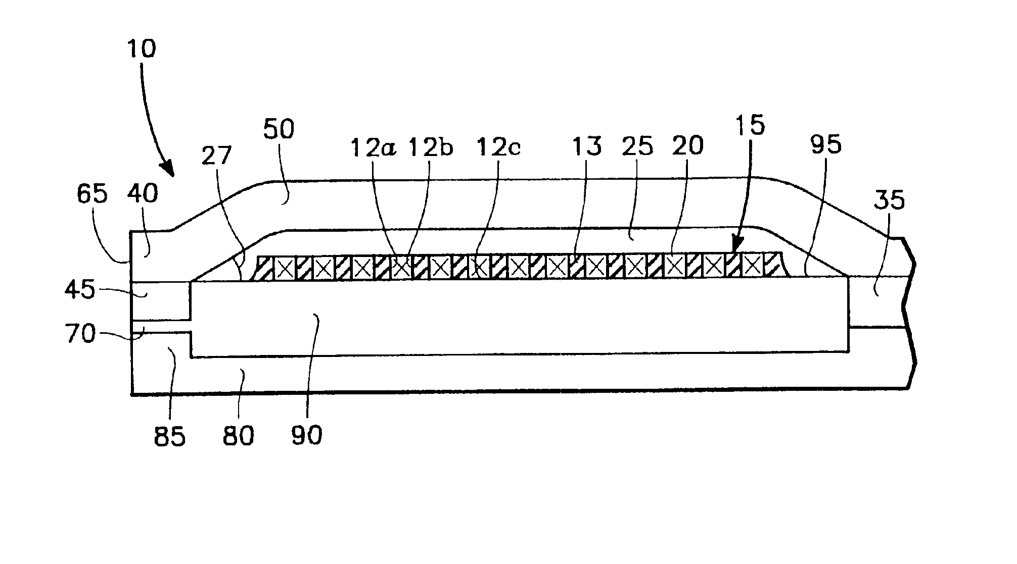
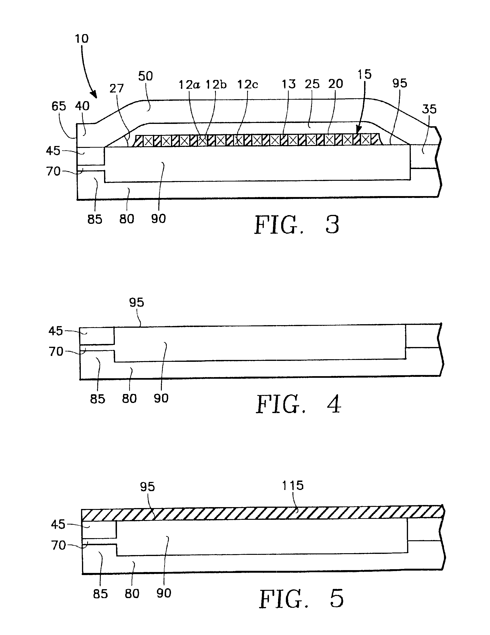
The present invention provides an improved thin film write head and method of fabrication that allows for an ultra-short yoke and / or an ultra-low stack height. The structure and method of the fabrication allow for a reduced yoke length and stack height by forming the conductor winding in trench etched from an insulation layer. The inorganic materials used for etching should be selected so that the etching process may be stopped, or slowed, at the underlying planarized layer. The conductor winding is formed on the underlying planarized layer by depositing conductor material so that it fills the trench. The inorganic materials should be deposited on the planarized surface of the conductor winding to insulate it from an overlying yoke. The present invention allows coil pitch to be reduced, resulting in more turns in a single layer of winding, and also reduces the length of the yoke and thus reduces the flux path length through the yoke. The improved aspect ratio allows more turns in a single layer of winding, and also reduces the stack height and the length of the yoke. The reduced number of curing cycles and improved heat dissipation over organic insulation also improve the reliability of the head.

Problems solved by technology

One problem with the above process is that it limits the minimum dimension of the winding.
Another drawback of the above process and structure is that it produces a coil structure with a high overall stack height.
Also, because cured photoresist is difficult to form in extremely thin layers, the cured photoresist insulation typically formed under the conductor winding significantly increases the overall stack height.
High stack height makes it difficult to control the width of the upper or P2 pole tip in certain write head designs, thus leading to increased track width sigma.
The increased stack height can cause problems with focusing and scattering during the exposure process, as well as problems of shadowing during pole trim process.
In addition, high stack height can cause reliability problems, such as cracking of the magnetic yoke material at the apex, or on the sloped surface between the top of the stack and the pole tip.
Also, the steep slope associated with the high stack height causes the magnetic properties of the yoke material to degrade.
Furthermore, thermal stability is a problem with the structure described above.
There is a large thermal expansion mismatch between the metal and the surrounding cured photoresist.
This can cause separation of yoke from the underlying insulation when the head is heated to higher temperature during manufacture, or operatation.

Method used


Image

  • Ultra-short yoke and ultra-low stack height writer and method of fabrication
  • Ultra-short yoke and ultra-low stack height writer and method of fabrication
  • Ultra-short yoke and ultra-low stack height writer and method of fabrication

Examples


Embodiment Construction

The Preferred Embodiments of the Present Invention

FIGS. 1-3&16

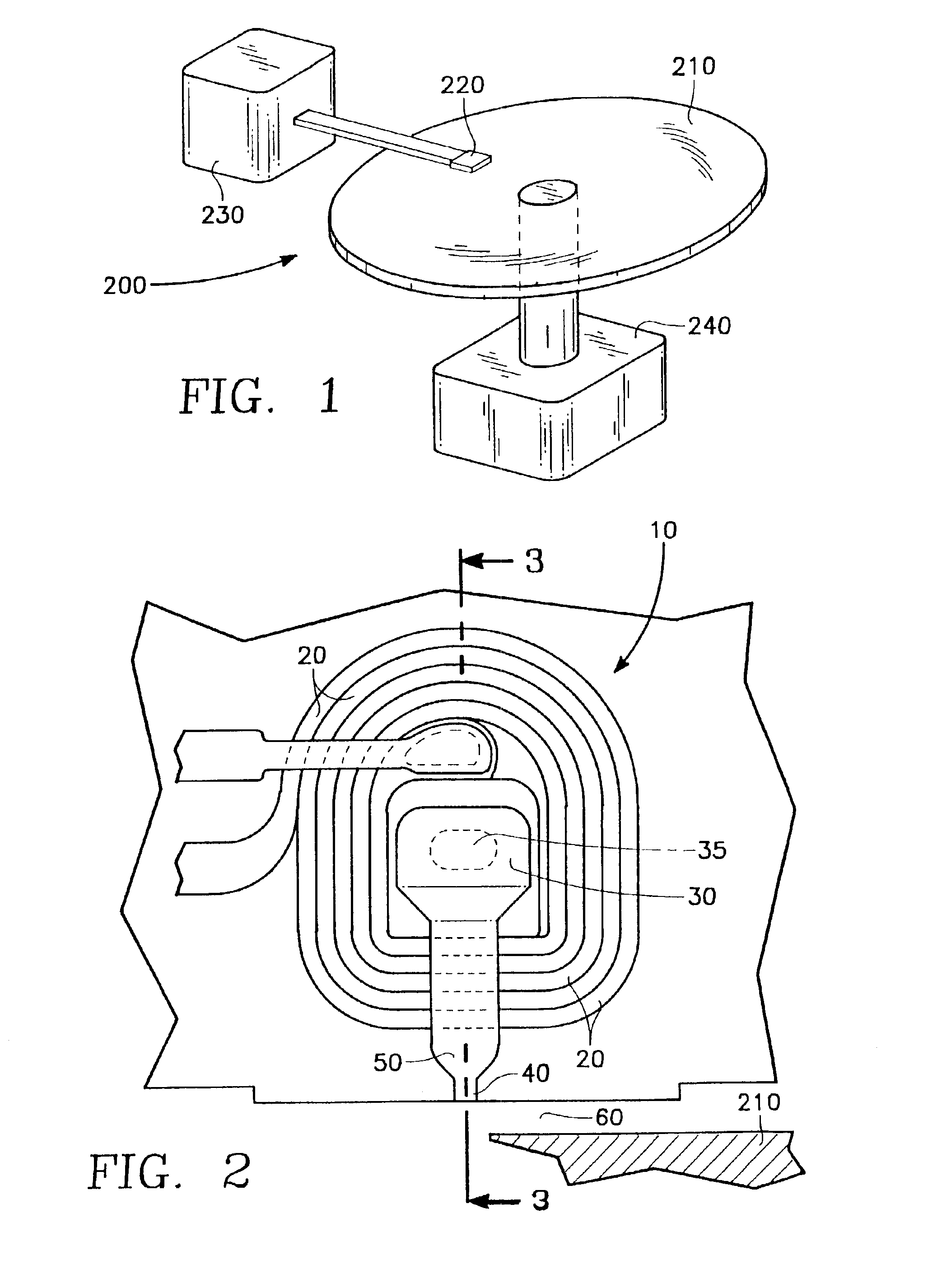
[0046]FIG. 1 shows the thin film write head of the present invention embodied in a disk type magnetic data storage and retrieval apparatus 200. The write head of the present invention is located within a merged head assembly 220 which rides above a magnetic storage media 210, depicted in FIG. 1 as a rotatable hard disk type storage media. The hard disk 210 is coupled to a motor 240 to provide rotation of the disk relative to the head assembly 220. An actuating means 230 may be used to position the head assembly 220 above the surface of the media 210 to read and write data in the form of magnetic bits from and to the media 210. The data storage and retrieval apparatus 200, typically has several hard disks 210 and several corresponding head assemblies 220.

[0047]FIG. 2 depicts a partial cut away top view of an embodiment of the thin film write head 10 of the present invention. Conductors 20 encircle a core 30 to produce magn...


PUM

PropertyMeasurementUnit
widthaaaaaaaaaa
aspect ratioaaaaaaaaaa
widthaaaaaaaaaa

Abstract

The present invention provides an improved thin film write head and method of fabrication capable of providing an ultra-short yoke and / or an ultra-low conductor winding stack. The present invention reduces yoke length and stack height by forming the conductor winding in a trench etched from an insulation layer, preferably formed of an inorganic insulation material. A thin resist mask is used to define the width of the trench while the etch process defines the depth. Preferably, the insulation layer is formed on a different inorganic insulation material to control the etch process, thus, the conductor winding may be formed on the underlying layer. The conductor winding preferably is formed by depositing conductor material so that it fills the trench and then planarizing, such as by chemical mechanical polish, to remove conductor material deposited outside the trench. An organic insulation layer, such as cured photoresist, may be deposited on the planarized surface of the conductor winding to insulate it from an overlying yoke. This overlying organic insulation layer may also define the apex angle of the head. The present invention may have multiple layers of conductor winding. The subsequent layers of conductor may be formed similar to the first layer, or may be formed with conventional photoresist processes and structures. The present invention may utilize any known pole structure or material.

Description

[0001]This application is a continuation of U.S. application Ser. No. 09 / 268,088 filed on Mar. 12, 1999, now U.S. Pat. No. 6,765,756; and claims priority therefrom pursuant to 35 U.S.C. § 120.BACKGROUND OF THE INVENTION[0002]1. Technical Field[0003]The present invention relates to the field of thin film write heads.[0004]2. Background Art[0005]Data is stored on magnetic media by writing on the magnetic media using a write head. Magnetic media can be formed in any number of ways, such as tape, floppy diskette, and hard disk. Writing involves storing a data bit by utilizing magnetic flux to set the magnetic moment of a particular area on the magnetic media. The state of the magnetic moment is later read, using a read head, to retrieve the stored information.[0006]Data density is determined by the amount of data stored on an area of magnetic media and depends on how much area must be allocated to each bit. Data on magnetic media is often stored in a line or track. Magnetic media often ...

Claims


Application Information

Patent Timeline
Patent Type & Authority Patents(United States)
IPC IPC(8): G11B5/31G11B5/17
CPCG11B5/3116G11B5/313G11B5/17G11B5/3163
Inventor HONG, LIUBOBARR, RONALD A.ZHOU, DASHUN STEVE
Owner WESTERN DIGITAL TECH INC
Learn More