
Closing device on a plastic injection molding machine

Inactive Publication Date: 2005-10-11
HEHL KARL
View PDF16 Cites 1 Cited by
  • Summary
  • Abstract
  • Description
  • Claims
  • Application Information

AI Technical Summary

Benefits of technology

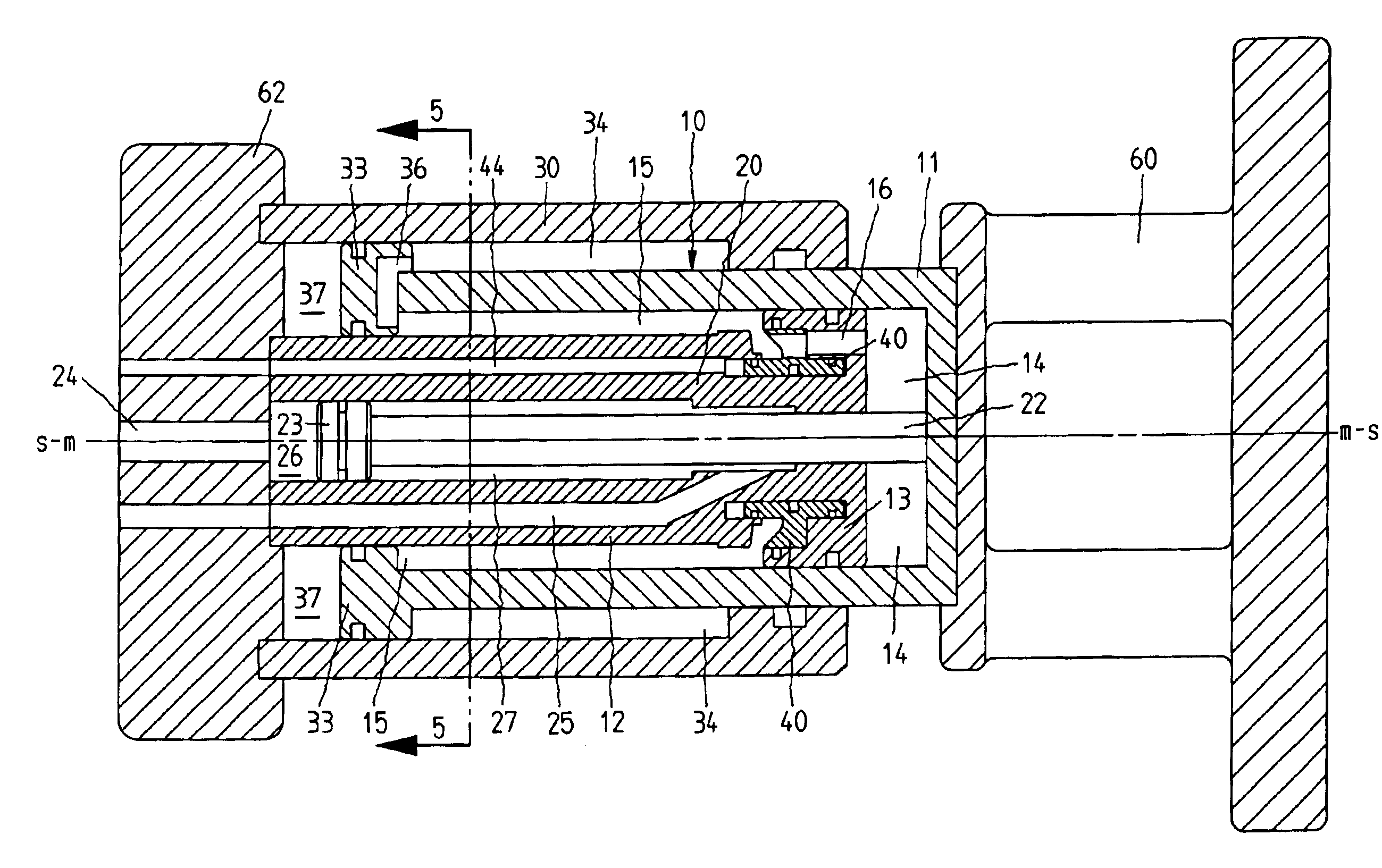
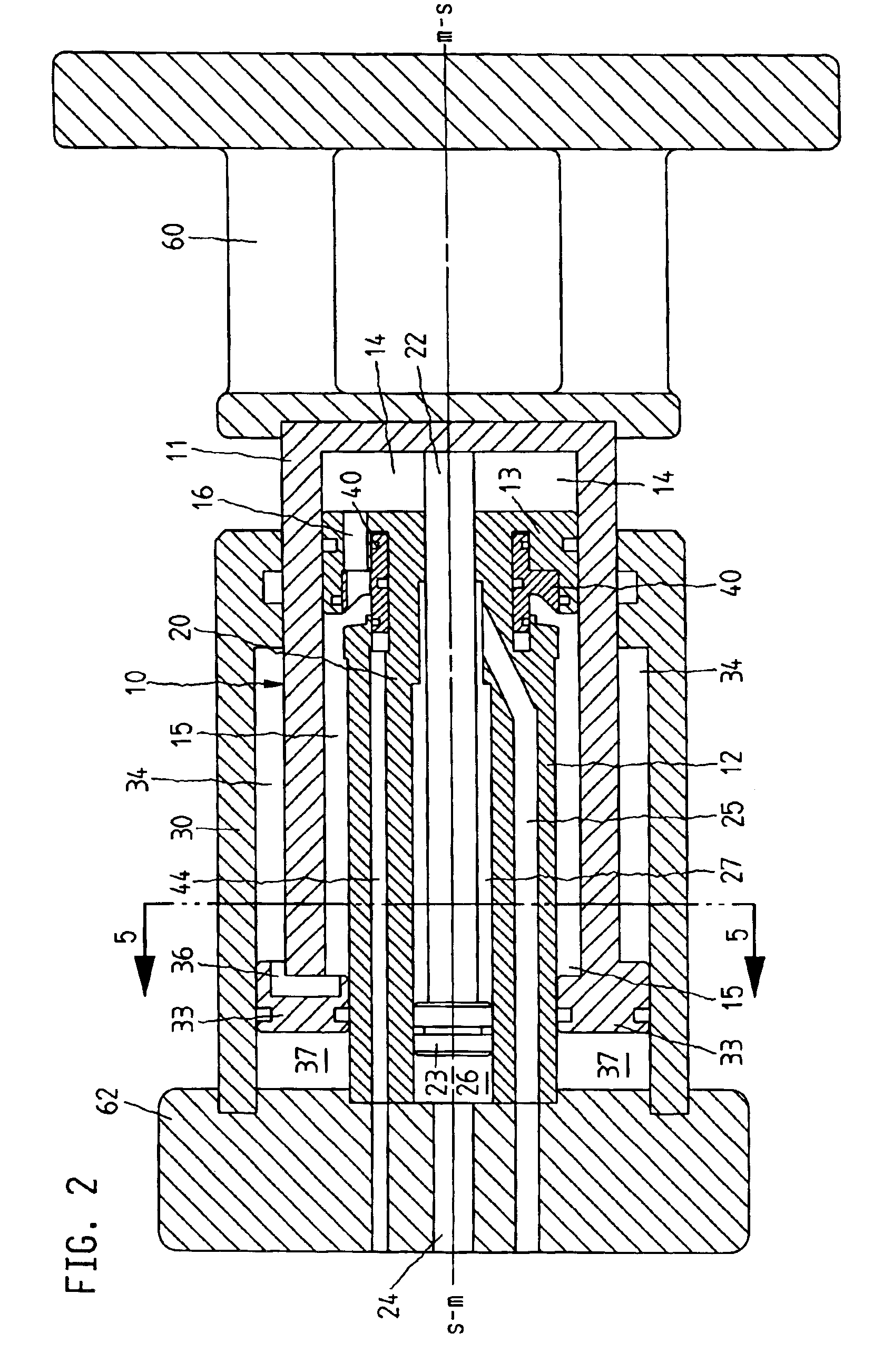
[0009]The closing device is so constructed that the cylinders of the closing device are stacked one inside the other. All of the cylinders are disposed concentrically relative to a central axis, so that a force is introduced concentrically relative to this central axis. In consequence, there is no longer an asymmetrical introduction of force within the closing device, so that a greater level of precision for the injection molding machine is ensured. At the same time, the volume of hydraulic medium required to build-up the pressure for keeping the mold closed is easily available, since it is expelled during the movement from the compensating cylinder chamber and low-pressure chamber to the high-pressure chamber. In consequence, rapid pressure build-up times are possible.
[0010]A space-saving construction results from one embodiment, since the appropriate overflow ducts are directly provided in the respective pistons of the compensating cylinder and pressure cylinder unit so that additional hydraulic pipes, which would have an adverse effect on the pressure build-up times, can be eliminated.

Problems solved by technology

In the case of such an embodiment, however, the volume of the compensating cylinders is limited and, in order to ensure a symmetrical force introduction, an appropriate amount of precision work is necessary.
In practical usage with delicate injection molded parts, however, it has in fact become apparent that, despite the symmetrical disposition of the pressure cylinders, irregularities in the build-up of the pressure for keeping the mold closed may occur in certain circumstances, above all after an appropriate service-life of the machine, such irregularities affecting the precision of the injection molded parts.
Although the compensating cylinder is a passive cylinder, it is apparent that the asymmetrical arrangement leads to an irregular application of force with the above-mentioned disadvantages.
This leads to a regular, considerable exchange of hydraulic medium, on the one hand, and this also increases the pressure build-up times, on the other hand.

Method used


Image

  • Closing device on a plastic injection molding machine
  • Closing device on a plastic injection molding machine
  • Closing device on a plastic injection molding machine

Examples


Embodiment Construction

[0016]The invention is now explained more detailed by way of example with reference to the accompanying drawings. However, the embodiments are only examples which should not restrict the inventive concept to one specific disposition.

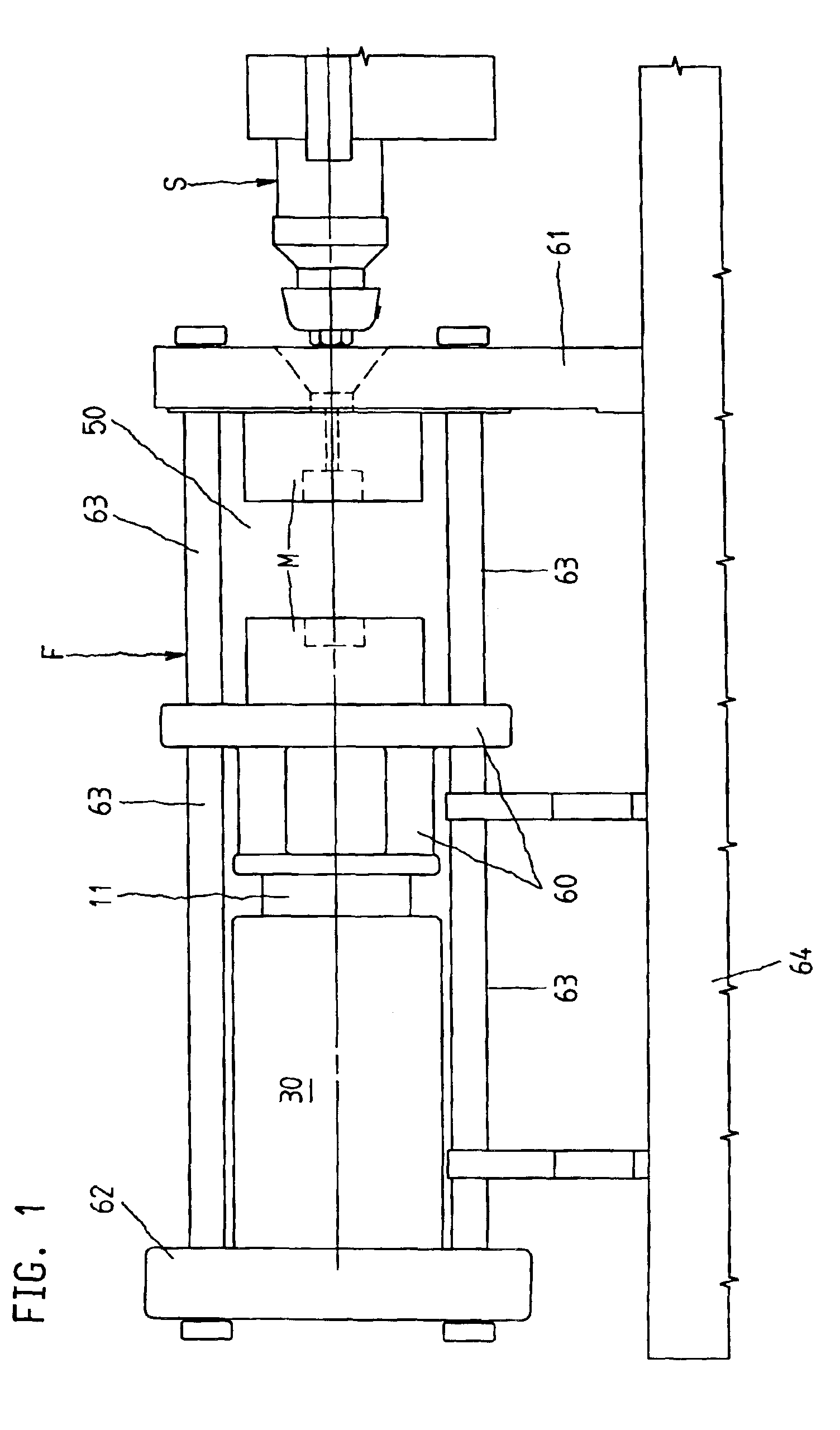
[0017]FIG. 1 illustrates the closing device for a mold dosing unit F of a plastic injection molding machine for processing plastics materials and other plasticizable substances, such as, for example, pulverulent substances or ceramic substances. The mold closing unit F is supported on a machine base 64 and includes a stationary mold carrier 61, a movable mold carrier 60, and a supporting element 62. The closing device is supported on the supporting element 62, of which device FIG. 1 illustrates the externally situated compensating cylinder 30 and the pressure cylinder 11, which serves as the piston for this compensating cylinder. During actuation of the pressure cylinder unit, which is to be discussed more fully hereinafter, the movable mold carrier 60 i...


PUM

PropertyMeasurementUnit
Pressureaaaaaaaaaa

Abstract

A closing device for a mold closing unit includes: at least one hydraulic pressure cylinder unit for generating a mold closing pressure on an injection mold which is accommodated in a mold clamping chamber; a pressure piston disposed in the pressure cylinder unit, a piston rod of the pressure piston is disposed along a central axis of the pressure cylinder unit, and the pressure piston separates a high-pressure chamber of the pressure cylinder unit from a low-pressure chamber thereof; an hydraulic driver cylinder, associated with the pressure cylinder unit, for closing the injection mold assembly, which drive cylinder is disposed concentrically relative to the central axis, and an actual cylinder of the drive cylinder is formed by the pressure piston of the pressure cylinder unit; and an hydraulic compensating cylinder, associated with the pressure cylinder unit, for receiving or respectively dispensing hydraulic medium, which comes from the pressure cylinder unit or respectively is to be dispensed to said pressure cylinder unit, and including a compensating cylinder chamber being in open communication with the low-pressure chamber of the pressure cylinder unit, wherein the compensating cylinder is likewise disposed concentrically relative to the central axis.

Description

CROSS-REFERENCE TO RELATED APPLICATIONS[0001]The present application claims the priority of German Patent Application 100 51 255.0, filed on Oct. 16, 2000, the disclosed contents of which are hereby also expressly made the subject-matter of the present application.FIELD OF THE INVENTION[0002]The invention relates to a closing device on the mold dosing unit of a plastic injection molding machine for processing plastics materials and other plasticizable substances.BACKGROUND OF THE INVENTION[0003]Such a closing device is known from DE 36 44 181 C1. In a pressure cylinder, which is disposed symmetrically relative to an axis of symmetry of the mold closing device, a drive cylinder is disposed in the piston of the pressure cylinder. The pressure piston of the pressure cylinder is displaceable jointly with the movable mold carrier. Likewise, the piston rod of the drive cylinder is disposed in a stationary manner. Two compensating cylinders are disposed diametrically relative to the pressu...

Claims


Application Information

Patent Timeline
IPC IPC(8): B29C45/67
CPCB29C45/6771
Inventor HEHL, KARL
Owner HEHL KARL
Learn More