Method and device for parameter independent buffer underrun prevention

a buffer and buffer technology, applied in the field of computer systems, network components and telecommunication devices, can solve problems such as data transmission delay, and achieve the effect of reducing latency and improving the overall data transfer ra

Inactive Publication Date: 2005-10-04
IBM CORP
View PDF9 Cites 16 Cited by
  • Summary
  • Abstract
  • Description
  • Claims
  • Application Information

AI Technical Summary

Benefits of technology

[0011]Starting from this, the object of the present invention is to provide a method and a device for parameter independent buffer underrun prevention in a data communication system with an improved overall data transfer rate, i.e., a reduced latency.BRIEF SUMMARY OF THE INVENTION
[0013]Thus, the method and the device according to the present invention manipulate the delay time via feedback control in a way, that it gets permanently decreased, to minimize latency, i.e., the period of time that data is held by a device before it is forwarded, or increased, to prevent buffer underrun. The delay time can be implemented as a number of delay cycles, which gets permanently decreased, as long as there is not the dangerous case, when the next decrease of the delay time would cause a buffer underrun, i.e., when the time gap is smaller than the specified tolerance value.
[0014]One major advantage of the method and device is that it adjusts to systems having dynamically varying parameters. Therefore, the present invention can advantageously be implemented in processors or other devices having a variable clock rate or transmission rate, e.g., due to power-saving-modes.

Problems solved by technology

While the use of buffers makes it possible to decouple processes so that a reader and a writer may operate at different speeds or on different sized blocks of data, they might be the reason for unwanted exceptional situations.
This may be due to a mismatch in the processing rates of the producing and consuming processes, or because the buffer is simply too small to hold all the data that must accumulate before a piece of it can be processed.
For example, in a text-processing tool that crunches a line at a time, a short line buffer can result in a loss as input from a long line overflows the buffer and overwrites data beyond it.
Both known approaches cause a delay in the data transmission.

Method used


Image

  • Method and device for parameter independent buffer underrun prevention
  • Method and device for parameter independent buffer underrun prevention
  • Method and device for parameter independent buffer underrun prevention

Examples


case b

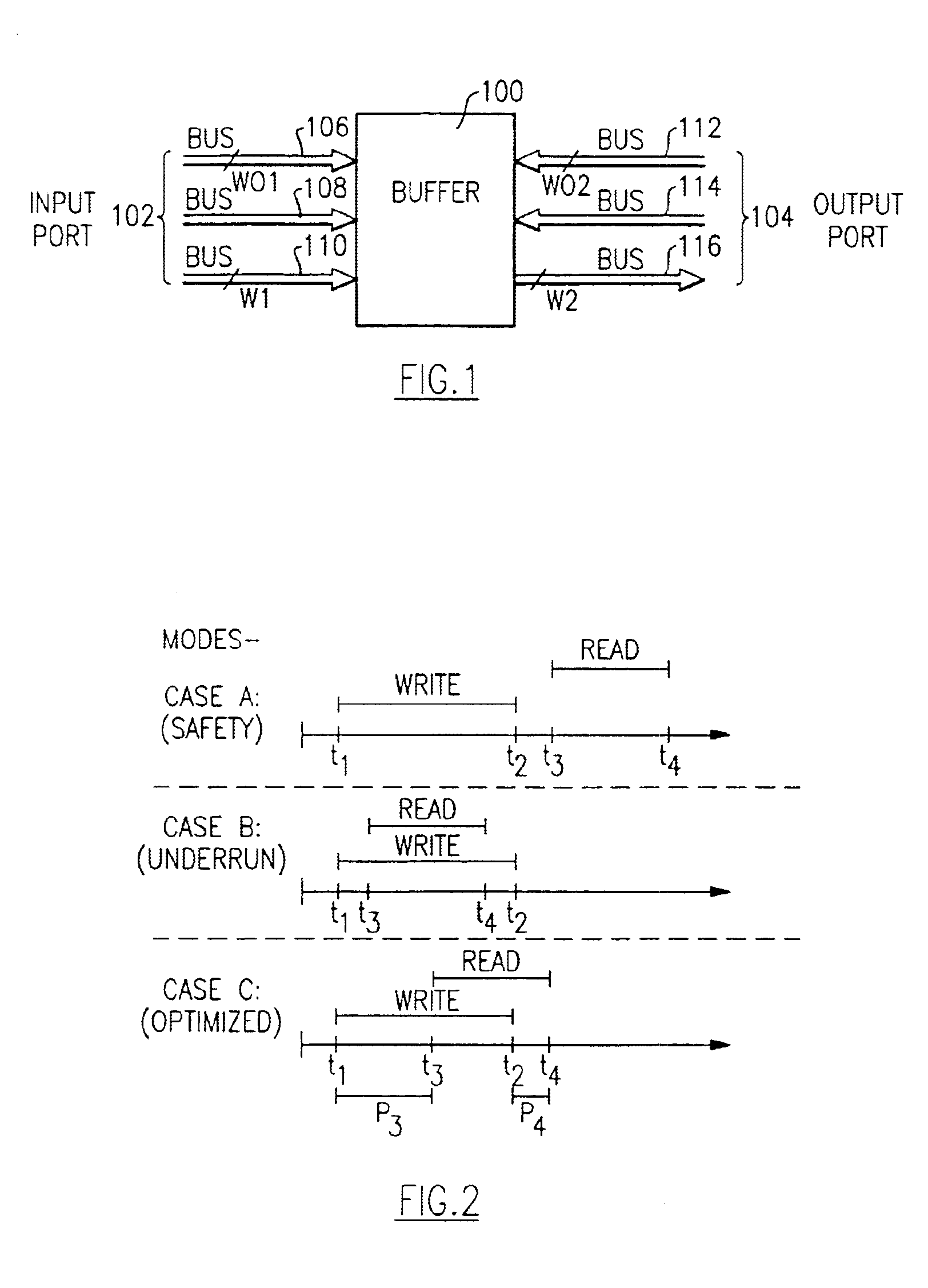
[0028 shows a buffer underrun situation that should be avoided. The read process start at time t3 is so early that the read process ends at time t4 before the time t2 when all data are written into the buffer. Thus, the read process reads out false data.

[0029]Still referring to FIG. 2, case C shows an optimized mode of operation according to the present invention. The read process starts at an instant of time t3, before time t2 when all write data has been written into the buffer. However, the start of the read transfer is chosen so that the end of the read transfer at time t4 is after the end of the write transfer at time t2. Since the mentioned times have to be whole-numbered multiples of a cycle time, there is a first period of time p4 at the end. Hence, in case C the latency p3, i.e., the period of time that passes before the input data get forwarded, is reduced, still avoiding an underrun condition as depicted in case B.

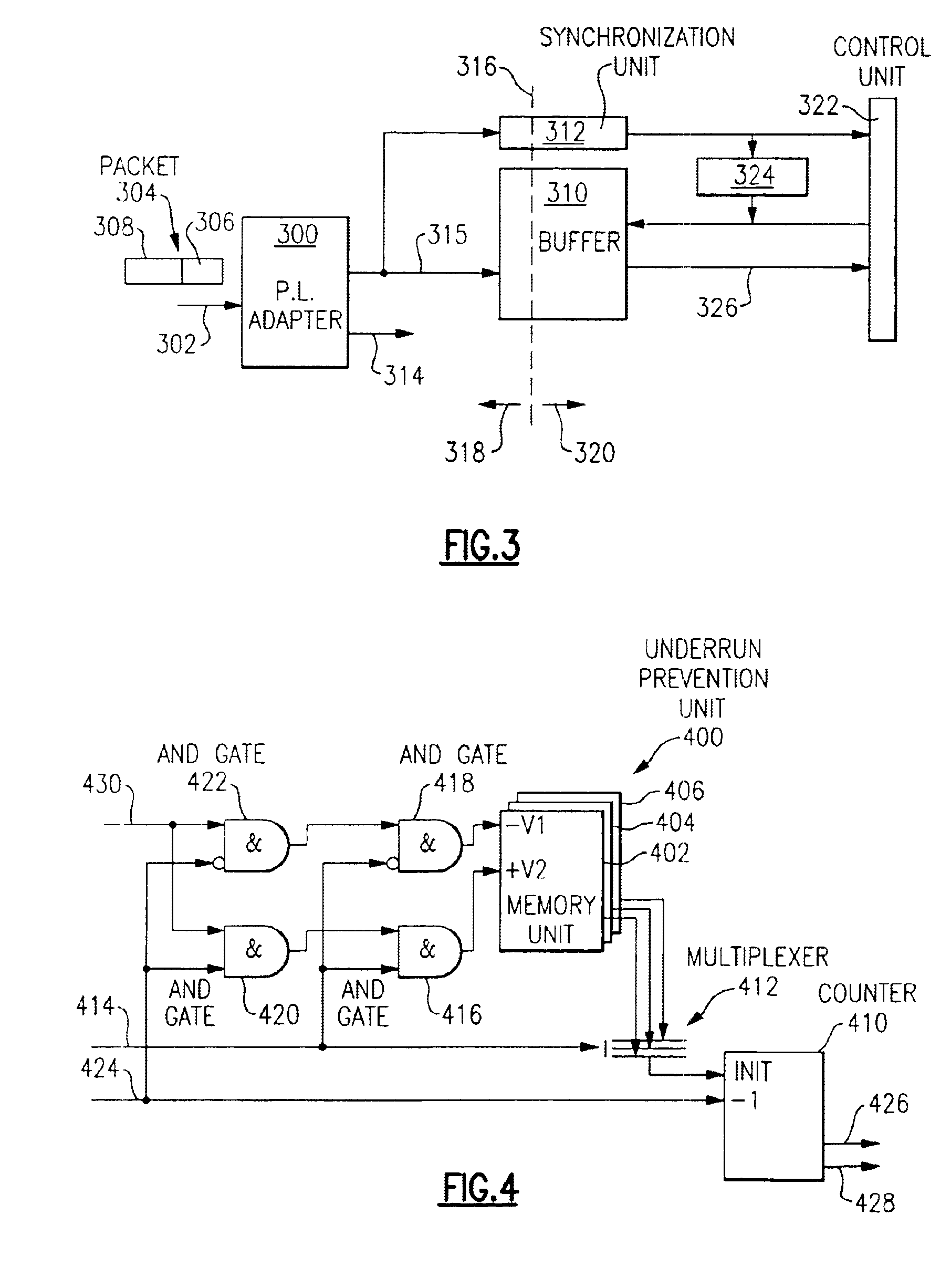
[0030]FIG. 3 depicts a high level block diagram of a data ...


PUM


Abstract

A method and device for parameter independent buffer underrun prevention in a data communication system includes a buffer for compensating for a difference in the rate of flow of data having a write port and a read port. After a commencement of writing data into the buffer, a predetermined delay time occurs. When the delay time has passed, reading data out from the buffer starts. Then the length of a time gap between the completion of writing data into the buffer and completion of reading data out from the buffer is determined. Finally, the length of the predetermined delay time is decreased by a first value if the length of the time gap is larger than a specified tolerance value and the length of the predetermined delay time is increased by a second value if the length of the time gap is smaller than the specified tolerance value. The provided method and device advantageously adjusts to systems having dynamically varying parameters, e.g., processors or other devices having a variable clock rate due to power-saving-modes.

Description

FIELD OF THE INVENTION[0001]The present invention relates generally to computer systems, network components and telecommunication devices. More particularly, the present invention relates to a method and a device for parameter independent buffer underrun prevention in a data communication system.BACKGROUND OF THE INVENTION[0002]A data communication system is a system or facility capable of providing information transfer between persons and equipment. The system usually consists of a collection of individual communication networks, transmission systems, relay stations, tributary stations, and terminal equipment capable of interconnection and interoperation so as to form an integrated whole. These individual components normally serve a common purpose, are technically compatible, employ common procedures, respond to some form of control, and generally operate in unison. Data communication systems can also be formed by a hardware connector used to link to other devices, or a convention ...

Claims


Application Information

Patent Timeline
IPC IPC(8): G06F5/06
CPCG06F5/06
Inventor FRITZ, ROLFHELMS, MARKUS MICHAEL
Owner IBM CORP
Why Eureka
Try Eureka