Optical unit, video display apparatus, and color switching method
a technology of video display and optical unit, applied in the direction of identification means, pulse techniques, instruments, etc., can solve the problems of short response time of liquid crystal, degraded light use efficiency, etc., and achieve the effect of improving contras
- Summary
- Abstract
- Description
- Claims
- Application Information
AI Technical Summary
Benefits of technology
Problems solved by technology
Method used
Image
Examples
first embodiment
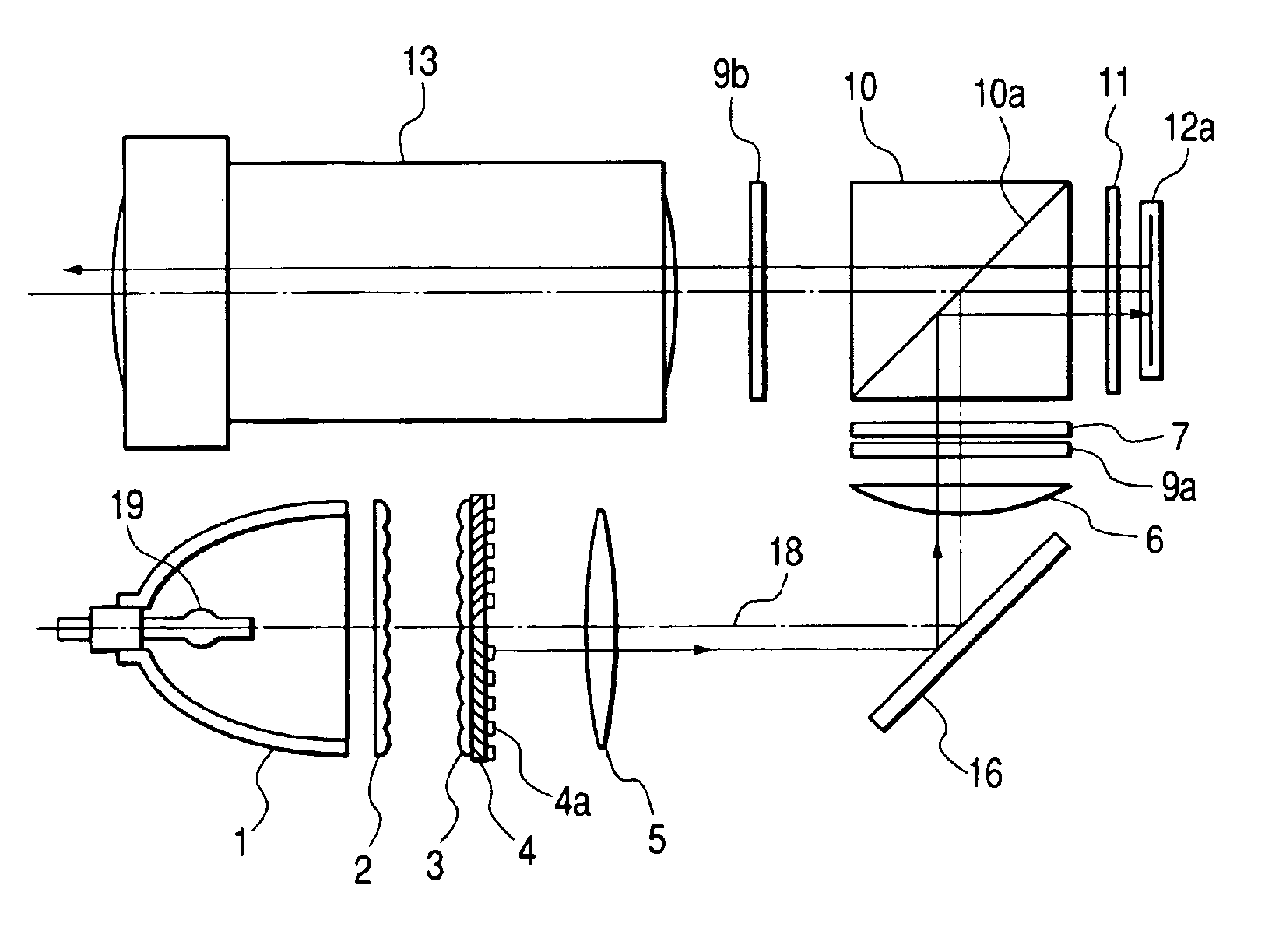
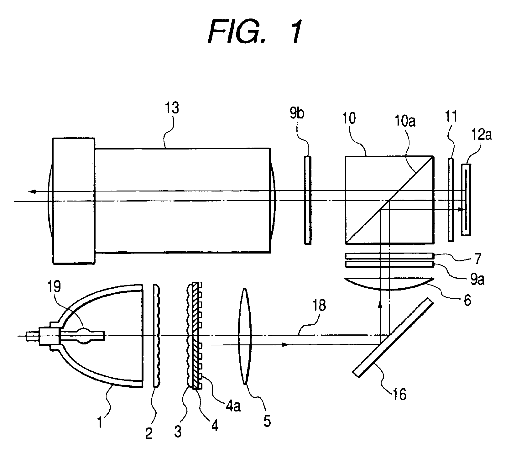
[0042]FIG. 1 is a schematic diagram showing the structure of an optical unit for a projection-type video display apparatus according to the present invention.
[0043]Referring to FIG. 1, a lamp for emitting light comprises a light source 19 and a reflector 1. Reference symbol 2 denotes a first lens array, reference symbol 3 denotes a second lens array, reference symbol 4 denotes a PBS, reference symbol 4a denotes a λ / 2 phase difference plate, reference symbol 5 denotes a condenser lens (collimator lens), reference symbol 14 denotes a reflecting mirror, reference symbol 6 denotes a condenser lens, reference symbol 7 denotes a optical characteristics switching element, and reference symbol 9a denotes a polarizing plate. Reference symbol 10 denotes a cuboid-shaped PBS comprising a PBS film 10a. Reference symbol 11 denotes λ / 4 phase difference plate, reference symbol 12a denotes a reflection-type liquid crystal panel for forming an optical image in accordance with the video signal, refere...
second embodiment
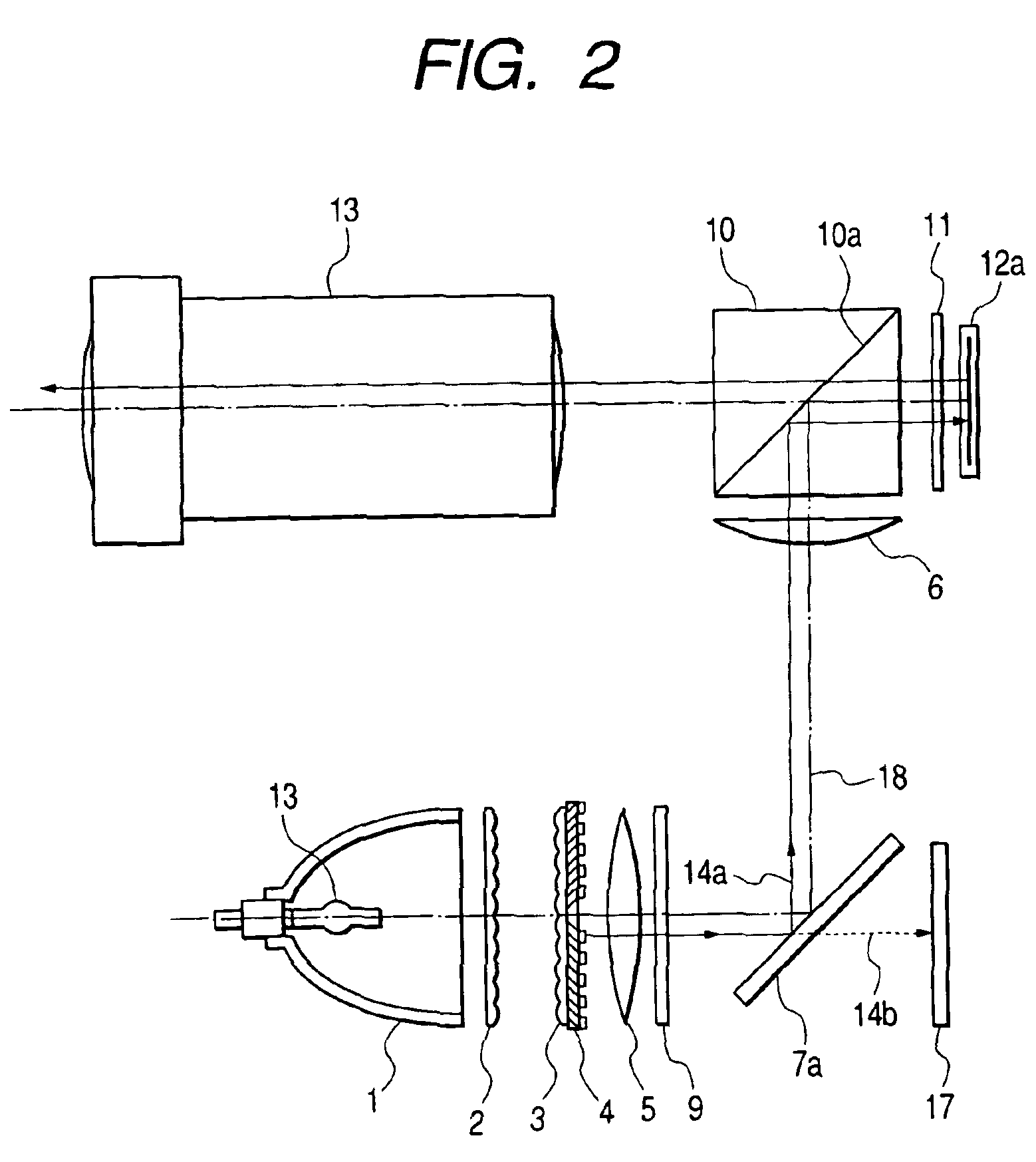
[0053]FIG. 2 is a schematic diagram showing the structure of an optical unit for a projection-type video display apparatus according to the present invention. Referring to FIG. 2, portions similar to those in FIG. 1 are designated by the same reference symbols and the description thereof is omitted.
[0054]Although the transmission-type optical characteristics switching element is used in FIG. 1 according to the first embodiment, a reflection-type optical characteristics switching element is used according to the second embodiment. A reflection-type optical characteristics switching element 7a separates colors by using light diffraction. The reflection-type optical characteristics switching element 7a separates colors into ON-light 14a and OFF-light 14b, and emits this light in different directions, respectively. The ON-light 14a shown by a continuous line is reflected to the optical characteristics switching element 7a and is outputted to a light path reaching the reflection-type liq...
third embodiment
[0056]FIG. 3 is a schematic diagram showing the structure of an optical unit for a projection-type video display apparatus according to the present invention. Referring to FIG. 3, portions similar to those in FIGS. 1 and 2 are designated by the same reference symbols and the description thereof is omitted.
[0057]According to the third embodiment, a light path is L-shaped. The polarizing plates 9a and 9c and the optical characteristics switching element 7 perform color separation because the PBS is not provided in the light path subsequent thereto. The optical characteristics switching elements is provided on the output side of the condenser lens 6. The polarizing plate 9c cuts OFF-light in a different polarizing direction. A transmission-type liquid crystal panel 12b is provided as a video display element. In the optical characteristics switching element 7, by using the group of polarizing rotation control elements, the R-, G-, and B-lights are sequentially incident on the transmissi...
PUM
| Property | Measurement | Unit |
|---|---|---|
| angle | aaaaa | aaaaa |
| reflecting angle | aaaaa | aaaaa |
| areas | aaaaa | aaaaa |
Abstract
Description
Claims
Application Information
 - R&D
- Intellectual Property
- Life Sciences
- Materials
- Tech Scout
- Unparalleled Data Quality
- Higher Quality Content
- 60% Fewer Hallucinations
Browse by: Latest US Patents, China's latest patents, Technical Efficacy Thesaurus, Application Domain, Technology Topic, Popular Technical Reports.
© 2025 PatSnap. All rights reserved.Legal|Privacy policy|Modern Slavery Act Transparency Statement|Sitemap|About US| Contact US: help@patsnap.com


