Controlling surface chemistry on solid substrates

a surface chemistry and solid substrate technology, applied in the direction of crystal growth process, after-treatment details, polycrystalline material growth, etc., can solve the problems of limited control, overly broad reaction zone or lower than desired aspect ratio, complicating experimental efforts to unravel the reaction mechanism, etc., and achieve high substrate surface temperatures

Inactive Publication Date: 2005-10-04
TUFTS UNIV
View PDF9 Cites 9 Cited by
  • Summary
  • Abstract
  • Description
  • Claims
  • Application Information

AI Technical Summary

Benefits of technology

[0016]The invention provides several advantages. For example, the new methods provide a highly collimated source of reactive precursor molecules. Moreover, the use of energetic gas-phase molecules reduces the need for high substrate surface temperatures. High surface temperatures can lead to undesirable effects such as surface or interlayer diffusion or unwanted side reactions.

Problems solved by technology

Existing methods typically afford limited control over the collimation of the deposited or etching materials impinging on the substrate, resulting, for example, in overly broad reaction zones or lower than desired aspect ratios (i.e., coating or etching depth divided by width).
Dissociative chemisorption is affected by a number of parameters that complicate experimental efforts to unravel the reaction mechanism.

Method used


Image

  • Controlling surface chemistry on solid substrates
  • Controlling surface chemistry on solid substrates
  • Controlling surface chemistry on solid substrates

Examples


example 1

Spatially Resolved Deposition of Laser-Excited Methane Molecules onto a Nickel Substrate

[0087]Experimental Procedure

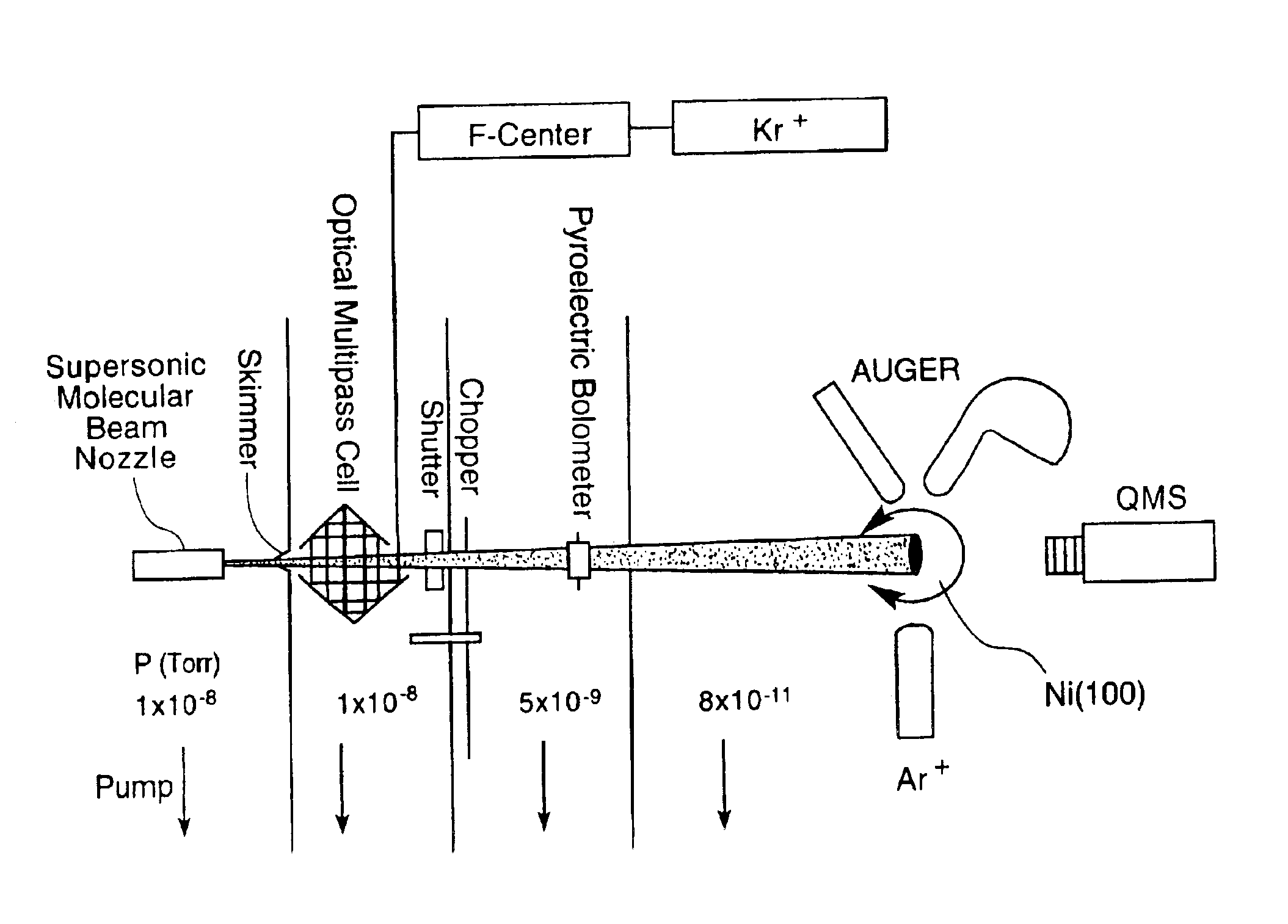
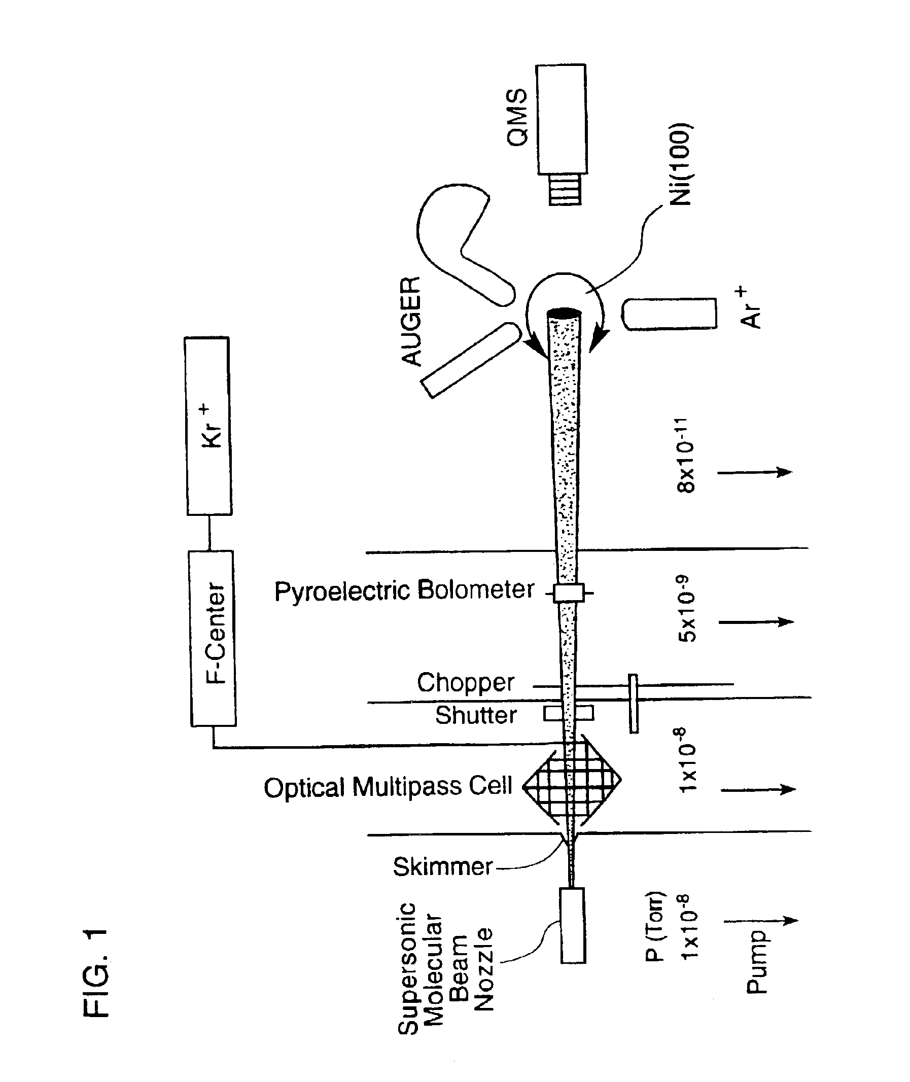
[0088]Supersonic molecular beams of methane (i.e., pure or seeded in hydrogen at a concentration of 0.25% or higher), were expanded from a heated nozzle source and triply differentially pumped prior to entering an ultrahigh vacuum (UHV) surface analysis chamber as described in McCabe et al. (Rev. Sci. Instrum., 7111:42-53, 2000). The UHV chamber housed a 1-cm diameter Ni(100) single crystal oriented to within 0.1° of the (100) plane, an electron gun and hemispherical electron energy analyzer for Auger electron spectroscopy measurements, a sputter gun for crystal cleaning, and a quadrupole mass spectrometer located on the molecular beam axis for time-of-flight analysis of the molecular beam. A schematic illustration of the apparatus appears in FIG. 1. The apparatus' design allows excitation of a significant fraction of the incident molecular beam into a single rovibrati...

example 2

Spatially Resolved Etching of a Semiconductor Surface by Laser-Excited Hydrogen Fluoride Molecules

[0099]A supersonic molecular beam of hydrogen fluoride (HF) diluted in an inert carrier gas expands from a nozzle source and is triply differentially pumped prior to entering an ultrahigh vacuum chamber containing a silicon substrate, as described in McCabe et al., (Rev. Sci. Instrum., 71(1):42-53, 2000). Infrared light crosses the molecular beam and excites HF molecules to a single rotational level of the first excited vibrational state. An orthogonal excitation geometry similar to that used in Example 1 allows a significant fraction of the HF molecules to be excited into a single excited rovibrational eigenstate using infrared laser radiation.

[0100]To quantify the enhanced reactivity of the laser excited molecules, a mass spectrometer in the chamber monitors the number of HF molecules scattered non-reactively from the silicon surface. The laser light irradiating the molecular beam is ...


PUM

PropertyMeasurementUnit
Fractionaaaaaaaaaa
Fractionaaaaaaaaaa
Timeaaaaaaaaaa

Abstract

By exposing precursor molecules traveling in a molecular beam to a narrow bandwidth laser beam (hu) tuned to a vibrational resonance frequency of the molecules and aimed orthogonal to the molecular beam (FIG. 6A), only those molecules having velocity (va) along trajectory (A) orthogonal to the laser beam are excited, becoming several orders of magnitude more reactive, affording a high degree of control over precise locations of reactions of molecules. Controlling a reaction on a surface of a solid substrate, includes; (a) obtaining a precursor molecule that includes (or can be reacted to form) species to be reacted with the substrate; (b) creating a molecular beam (eg., supersonic) that includes the precursor molecule; (c) vibrationally exciting the molecule with the laser beam tuned to a vibrational resonance frequency of the molecule; and (d) causing the exciting molecule to impinge on the substrate, enabling reactions (deposition, etching . . . ) of the species with the substrate.

Description

[0001]This application claims the benefit of Provisional Application No. 60 / 189,604, filed Mar. 15, 2000.STATEMENT AS TO FEDERALLY SPONSORED RESEARCH[0002]This invention was made with Government support under grant number CHE-9703392, awarded by the National Science Foundation. The Government has certain rights in this invention.FIELD OF THE INVENTION[0003]The invention relates to methods for controlling surface chemistry on solid substrates.BACKGROUND OF THE INVENTION[0004]Chemical vapor deposition and submicron etching techniques are widely applied, for example, in the manufacture of semiconductors and chips. Existing methods typically afford limited control over the collimation of the deposited or etching materials impinging on the substrate, resulting, for example, in overly broad reaction zones or lower than desired aspect ratios (i.e., coating or etching depth divided by width). There is considerable interest in developing spatially resolved deposition processes.[0005]Gas-surf...

Claims


Application Information

Patent Timeline
IPC IPC(8): H01L21/02H01L21/31H01S1/00C23C16/04C23C16/26C23C16/44C23C16/455C23C16/48C30B25/10C30B33/00C30B33/04
CPCC23C16/04C23C16/047C23C16/26C23C16/4551C23C16/483C30B25/105C30B33/00C30B33/04C30B29/36
Inventor UTZ, ARTHUR L.JUURLINK, LUDO B. F.
Owner TUFTS UNIV
Why Eureka
Try Eureka