
Vehicle periphery monitoring apparatus and method of determining type of object for use in vehicle periphery monitoring apparatus

a technology of vehicle periphery and monitoring apparatus, which is applied in the field of vehicle periphery monitoring apparatus, can solve the problems of high price of the monitoring apparatus with a pair of left and right infrared cameras, and achieve the effect of easy identification and high surface temperatur

Inactive Publication Date: 2013-09-12
HONDA MOTOR CO LTD
View PDF1 Cites 55 Cited by
  • Summary
  • Abstract
  • Description
  • Claims
  • Application Information

AI Technical Summary

Benefits of technology

The present invention provides a vehicle periphery monitoring apparatus and method that can accurately distinguish between another vehicle and a pedestrian. This is achieved by detecting a high-luminance area that is greater in area than the pedestrian head candidate and has a horizontal length equal to or greater than a prescribed width. This allows for a more accurate identification of objects in the vehicle periphery monitoring apparatus.

Problems solved by technology

However, since such vehicle periphery monitoring apparatuses with a pair of left and right infrared cameras are expensive, they have been incorporated in limited luxury cars only.

Method used


Image

  • Vehicle periphery monitoring apparatus and method of determining type of object for use in vehicle periphery monitoring apparatus
  • Vehicle periphery monitoring apparatus and method of determining type of object for use in vehicle periphery monitoring apparatus
  • Vehicle periphery monitoring apparatus and method of determining type of object for use in vehicle periphery monitoring apparatus

Examples


Embodiment Construction

[0036]Preferred embodiments of the present invention will be described in detail below with reference to the drawings.

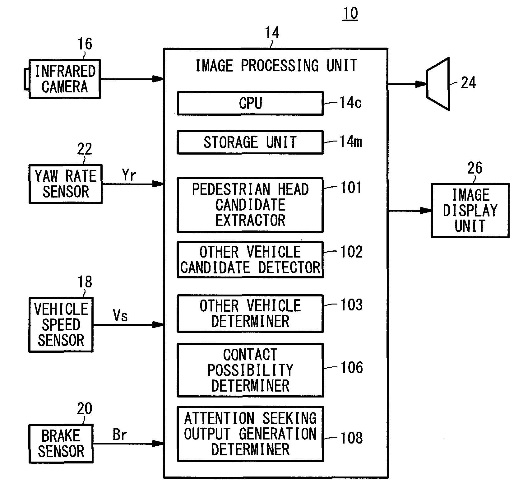
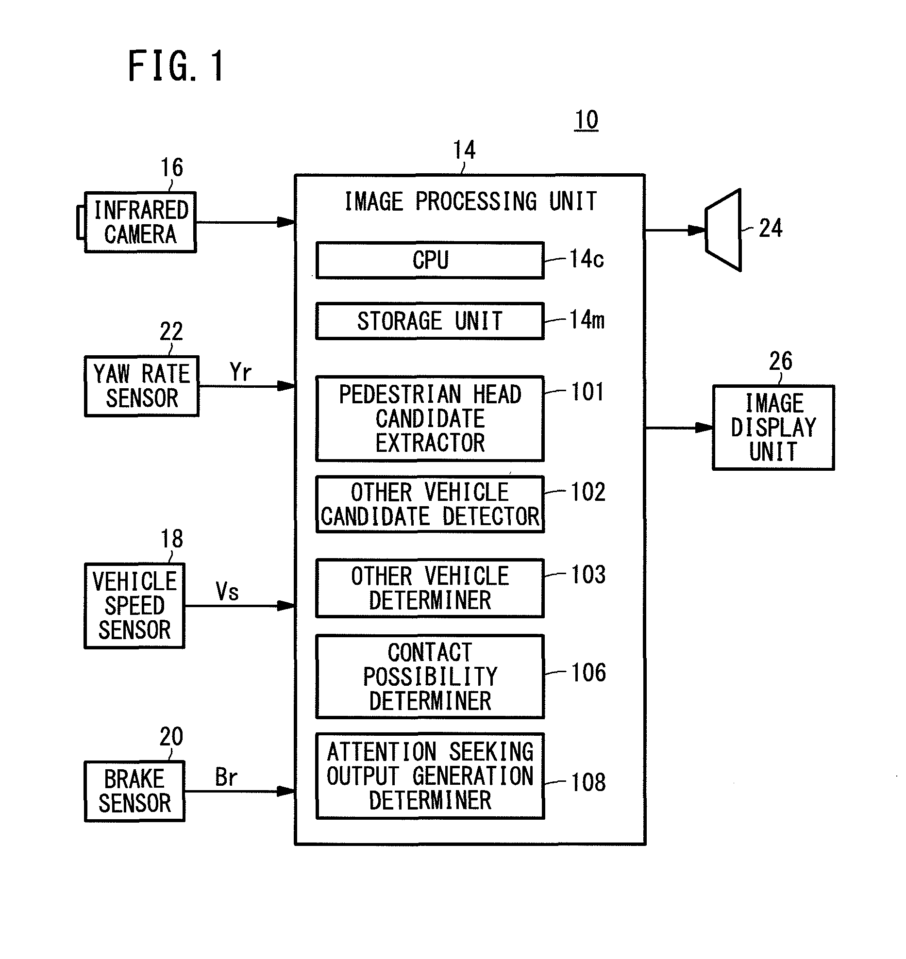
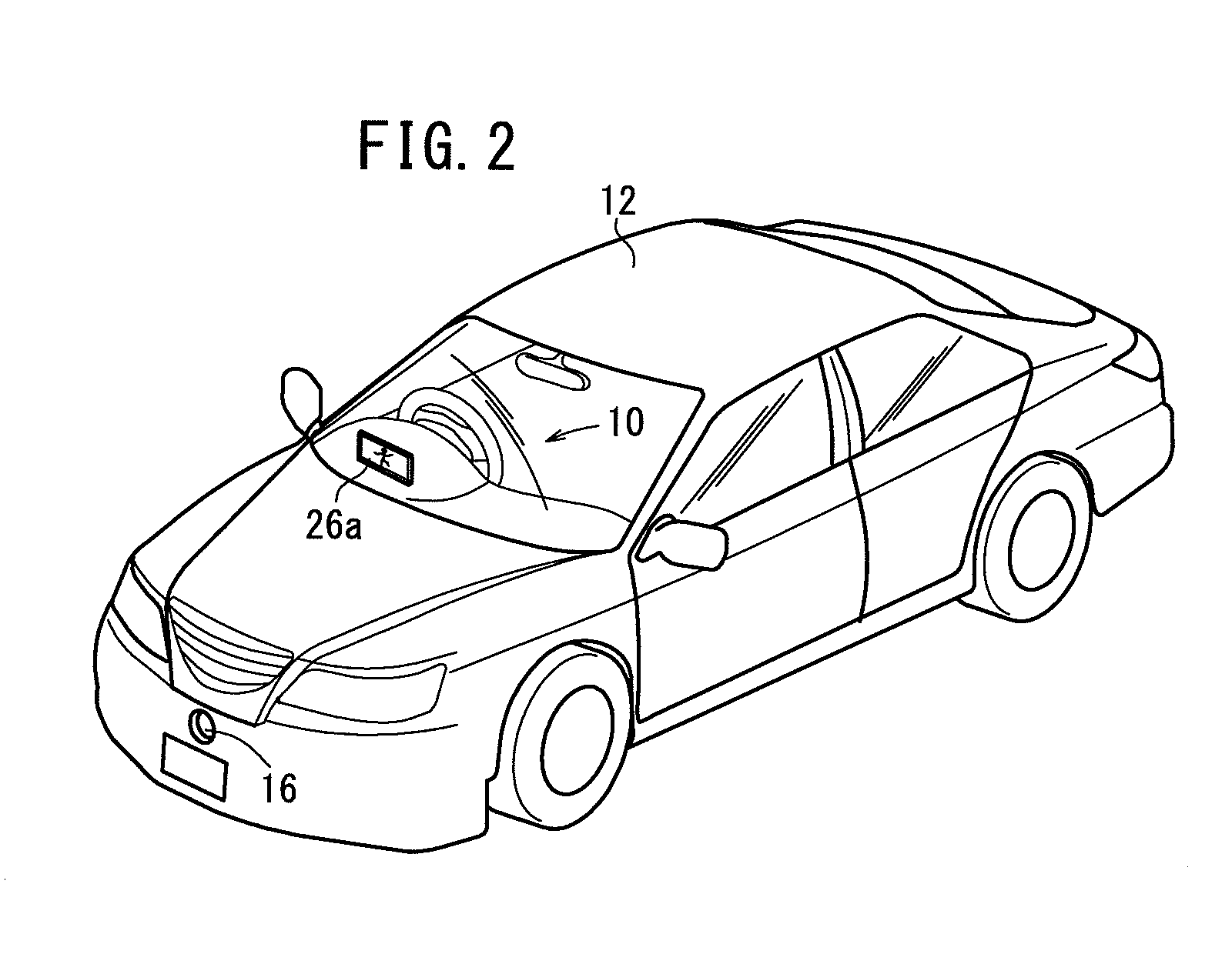
[0037]FIG. 1 shows in block form a vehicle periphery monitoring apparatus 10 according to an embodiment of the present invention, and FIG. 2 shows in perspective a vehicle (hereinafter also referred to as “driver's own vehicle”) 12 which incorporates the vehicle periphery monitoring apparatus 10 shown in FIG. 1.

[0038]As shown in FIGS. 1 and 2, the vehicle periphery monitoring apparatus 10 includes an image processing unit 14 for controlling the vehicle periphery monitoring apparatus 10, a single (monocular) infrared camera 16 (image capturing device) connected to the image processing unit 14, a vehicle speed sensor 18 for detecting a vehicle speed Vs of the vehicle 12, a brake sensor 20 for detecting a depressed amount (brake depressed amount) Br of a brake pedal which is operated by the driver of the vehicle 12, a yaw rate sensor 22 for detecting a yaw rate Yr of th...


PUM


Abstract

If a pedestrian head candidate extractor extracts a light as a pedestrian head candidate, then when an other vehicle candidate detector detects a horizontal high-luminance area which is greater in area than the light extracted as the pedestrian head candidate, within a prescribed range beneath the horizontal position of the light, an other vehicle determiner determines the light extracted as the pedestrian head candidate as part of another car.

Description

CROSS-REFERENCE TO RELATED APPLICATION[0001]This application is based upon and claims the benefit of priority from Japanese Patent Application No. 2012-053962 filed on Mar. 12, 2012, the contents of which are incorporated herein by reference.BACKGROUND OF THE INVENTION[0002]1. Field of the Invention[0003]The present invention relates to a vehicle periphery monitoring apparatus for monitoring the periphery of a vehicle based on an image captured by an infrared camera mounted on the vehicle, and more particularly to a vehicle periphery monitoring apparatus and a method of determining the type of an object for use in such a vehicle periphery monitoring apparatus, which are suitable for use when the vehicle is driving at night or in dark places.[0004]2. Description of the Related Art[0005]As disclosed in Japanese Laid-Open Patent Publication No. 2003-284057 (hereinafter referred to as “JP2003-284057A”), there has heretofore been known a vehicle periphery monitoring apparatus incorporate...

Claims


Application Information

Patent Timeline
Patent Type & Authority Applications(United States)
IPC IPC(8): H04N5/33
CPCH04N5/33G06K9/00805G06K9/00825G06V20/58G06V20/584H04N23/20
Inventor NAGAOKA, NOBUHARUAIMURA, MAKOTO
Owner HONDA MOTOR CO LTD
Learn More