
Linear guide

a line-guide, linear technology, applied in the direction of mechanical equipment, couplings, transportation and packaging, etc., can solve the problem that the axial relativeness of the two shaft parts can only be limited, and achieve the effect of enhancing the load-carrying capacity of the bearing

Inactive Publication Date: 2005-09-27
INA SCHAEFFLER KG
View PDF19 Cites 41 Cited by
  • Summary
  • Abstract
  • Description
  • Claims
  • Application Information

AI Technical Summary

Benefits of technology

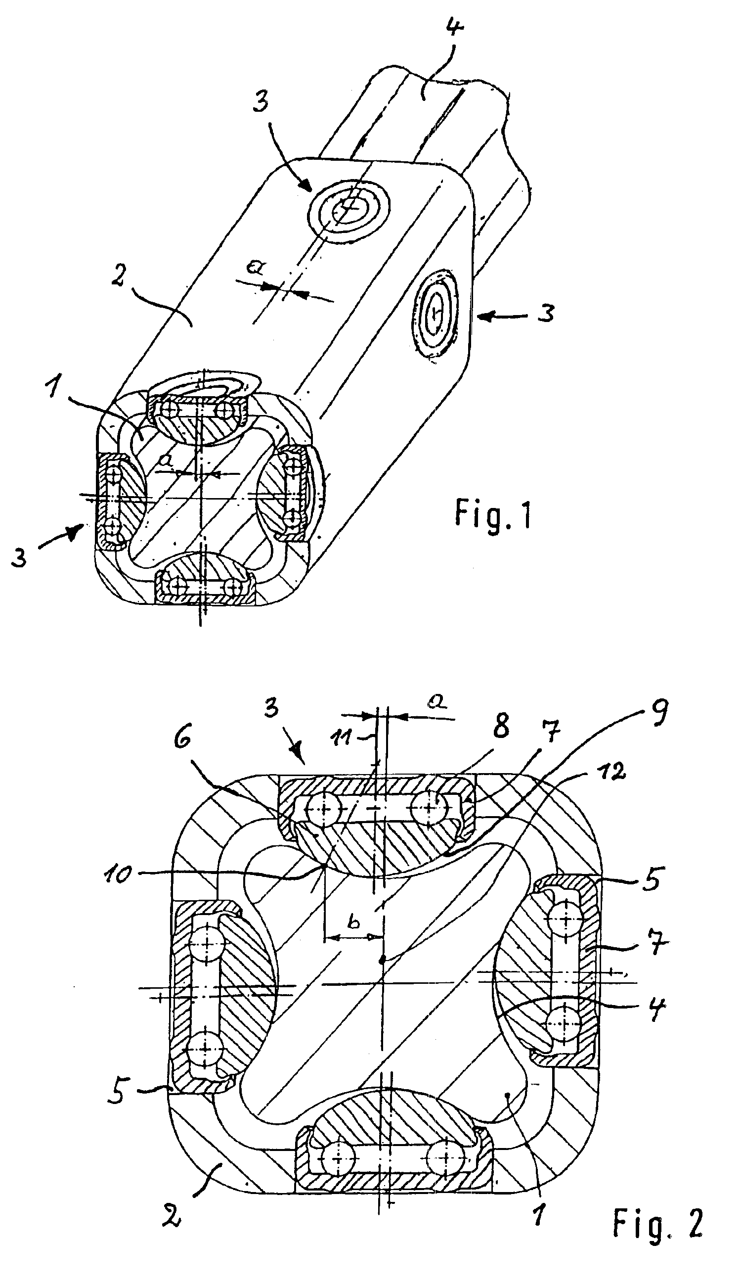
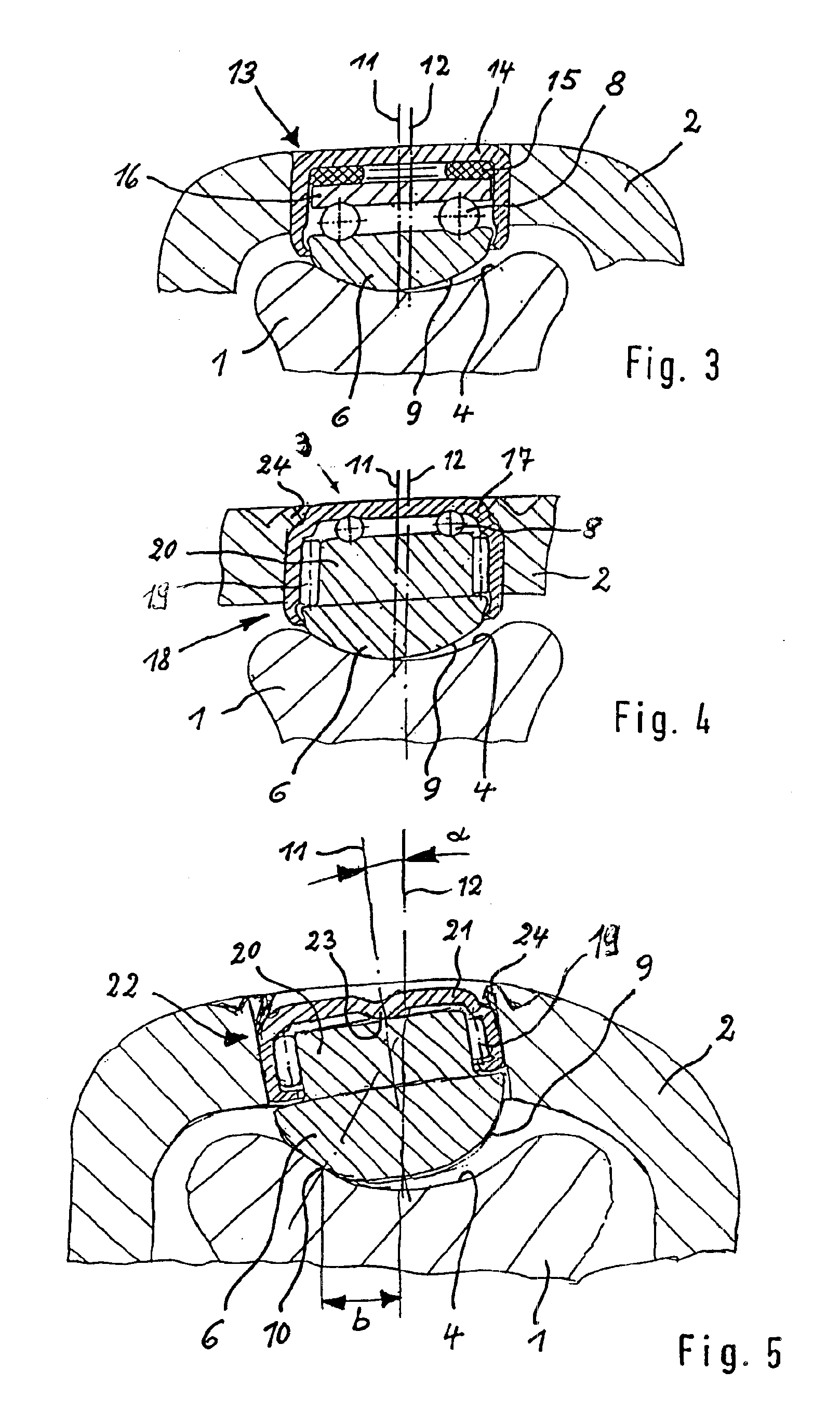
[0010]As a consequence of the parallel shift of the bushing axis in relation to the shaft center, and in view of the convex cup-shaped surface of the bearing member and its support on the surface area of the shaft, the contact point of the shaft is shifted so as to establish a rotation lever which causes a rotation of the bearing member, when the shaft moves linearly. An adverse impact of dimensional tolerances can be eliminated by a tolerance-independent positioning of the axial rolling bearing in relation to the shaft.
[0012]Hereby, the center axis of the needle bushing may be shifted in parallel relationship to the normal at an offset, or, as an alternative, the center axis of the needle bushing may be inclined at an angle in relation to the normal to have a same effect.
[0015]The shaft of the linear guide may be a steering column spindle of polygonal configuration, e.g. of triangular, tetragonal, or square cross section, wherein the surface area has a concave shape, and wherein at least two longitudinal sides adjoining one another in circumferential direction have each a concave surface area. As a consequence of the concave surface areas, the load-carrying capability of the bearing is enhanced.
[0016]The invention allows the use of complete bearing kits with rolling bodies and raceways, so that it is no longer necessary to incorporate the raceways the housing.

Problems solved by technology

Moreover, both shaft parts can be moved axially relative to one another only in a limited manner.

Method used


Image

  • Linear guide
  • Linear guide
  • Linear guide

Examples


Embodiment Construction

[0023]Throughout all the Figures, same or corresponding elements are generally indicated by same reference numerals. These depicted embodiments are to be understood as illustrative of the invention and not as limiting in any way. It should also be understood that the drawings are not necessarily to scale and that the embodiments are sometimes illustrated by graphic symbols, phantom lines, diagrammatic representations and fragmentary views. In certain instances, details which are not necessary for an understanding of the present invention or which render other details difficult to perceive may have been omitted.

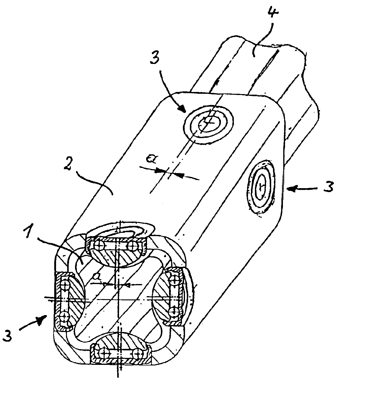
[0024]Turning now to the drawing, and in particular to FIG. 1, there is shown a perspective illustration of one embodiment of a linear guide according to the present invention, including a shaft 1, a housing 2, and a plurality of axial rolling bearings, generally designated by reference numeral 3 and constructed as ball bearings. The shaft 1 has a generally square cross sectio...


PUM


Abstract

In a linear guide for transmitting a torque between a tubular housing, rotatable about a longitudinal axis, and a shaft, received in the housing and movable in the direction of the axis in relation to the housing, a plurality of axial rolling bearings are received in the housing in surrounding relationship to the shaft. The axial rolling bearings are disposed in two radial planes in axial spaced-apart relationship, wherein the axial rolling bearings in each of the two radial planes have each two bearing members and a set of rolling bodies disposed between the bearing members. One bearing member is constructed as bushing retained in the housing and defining a center axis which is shifted parallel at an offset to a normal upon a longitudinal shaft axis, while the other bearing member has a cup-shaped configuration to define a convex surface for support by a surface area of the shaft.

Description

CROSS-REFERENCES TO RELATED APPLICATIONS[0001]This application is a continuation of prior filed copending PCT International application no. PCT / EP02 / 00675, filed Jan. 24, 2002, on which priority is claimed under 35 U.S.C. §120, the disclosure of which is hereby incorporated by reference.[0002]This application claims the priority of German Patent Application, Ser. No. 101 06 982.0, filed Feb. 15, 2001, pursuant to 35 U.S.C. 119(a)-(d), the disclosure of which is incorporated herein by reference.BACKGROUND OF THE INVENTION[0003]The present invention relates to a linear guide for transmitting a torque between a tubular housing, which is defined by a longitudinal axis and rotatable about the longitudinal axis, and a shaft, which is received in the housing and movable in the direction of the axis in relation to the housing.[0004]Linear guides for transmission of torques are used in the automobile industry for example for guiding racks or for guiding steering spindles in a steering column...

Claims


Application Information

Patent Timeline
IPC IPC(8): B62D1/18F16C29/04F16D3/02F16D3/06B62D1/185F16C29/02
CPCB62D1/185F16C29/04F16D3/065F16C2326/24F16D3/06
Inventor ZERNICKEL, ALEXANDERDOPPLING, HORST
Owner INA SCHAEFFLER KG
Learn More