
Automated calibration of I/O over a multi-variable eye window

a multi-variable, automatic calibration technology, applied in the field of electronic systems, can solve the problems of critical timing differences between the various signal lines, changing the voltage level may affect the setup/hold time, and changing the setup/hold time may affect the voltage level

Inactive Publication Date: 2005-09-13
ORACLE INT CORP
View PDF12 Cites 28 Cited by
  • Summary
  • Abstract
  • Description
  • Claims
  • Application Information

AI Technical Summary

Benefits of technology

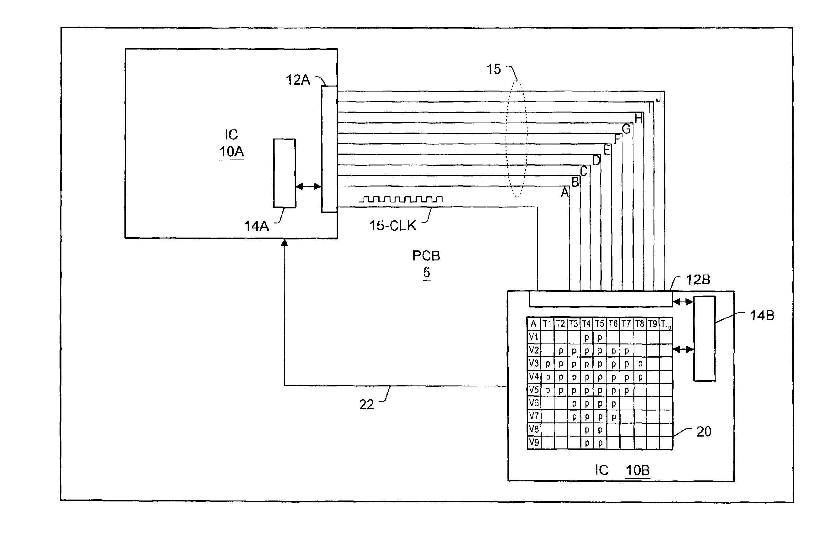
[0013]In various embodiments, the data structure may be multi-dimensional. For example, a table may include columns corresponding to voltage levels, rows corresponding to delay times, and a third dimension that corresponds to a third parameter, such as termination. Thus, each element of the data structure may correspond to a voltage level and a delay time for a given signal line. It should be noted that additional parameters may also be included (as will be discussed below), and thus the data structure may include any number of dimensions. The data structure may take on any shape or organization (e.g. a cube, etc.) as necessary. As with the table, other embodiments of the data structure may also be compressed in size. The use of a multi-dimensional data structure may allow for optimization among a larger number of variables.

Problems solved by technology

Thus, since the data must be latched simultaneously, the timing differences between the various signal lines becomes critical.
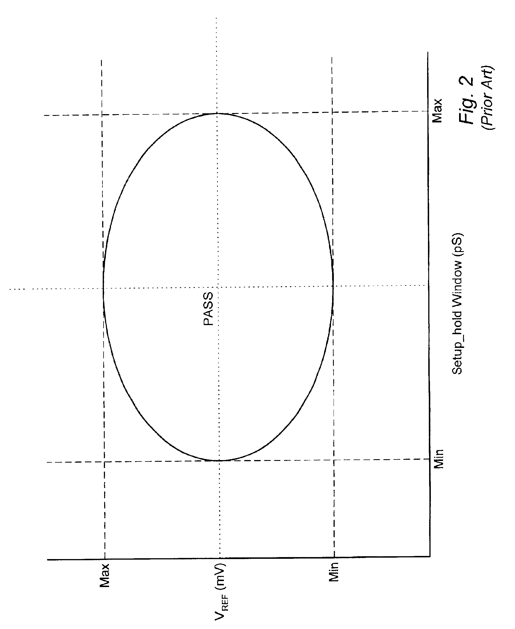
Furthermore, changing the voltage levels may affect the setup / hold times, and changes to the setup / hold times may affect the voltage levels.
This may involve a manual process of setting the voltage and timing delays for signal transmissions that occur in the system.
Thus, changes in the operating conditions of the system may result in lower margins of operation for the voltage levels and / or the timing delays.

Method used


Image

  • Automated calibration of I/O over a multi-variable eye window
  • Automated calibration of I/O over a multi-variable eye window
  • Automated calibration of I/O over a multi-variable eye window

Examples


Embodiment Construction

[0023]Turning now to FIG. 3, a drawing of one embodiment of a printed circuit board having two IC's, wherein the second IC includes a table is shown. PCB 5 includes a first IC 10A and a second IC 10B, coupled by a plurality of signal lines 15. The embodiment shown includes 10 signal lines, 15A through 15J, which provide electrical coupling between the IC's through transmit port 12A and receiver port 12B. The embodiment shown is a source synchronous I / O system, and thus clock line 15-CLK is used to provide a clock signal for synchronizing data transmissions. Other embodiments which are not source synchronous are possible and contemplated. Transmitter 12A may generate a clock signal which may be received by receiver 12B, which may latch data received over the signal lines on one of the clock edges. Other communications links, such as communications link 22, may be present and allow second IC 10B to send information to first IC 10A. Communications link 22 may include one or more signal...


PUM


Abstract

A method and apparatus for automated calibration of I / O over a multi-variable eye window is provided. A transmitter may conduct data transmissions to a receiver of an integrated circuit (IC) over a plurality of signal lines. The data transmissions may be conducted according to a certain parameters or sets of parameters. Parameters may include voltage levels at which signals are transmitted or timing delays. The receiver may determine whether the correct data value was received over each signal line. The results may be recorded in a storage mechanism in the same IC as the receiver. The storage mechanism may, for each signal line, store a pass / fail result corresponding to the particular parameters for the data transmission. The system may select the parameters which subsequent transmissions are to be conducted over each of the plurality of signal lines from the storage mechanism.

Description

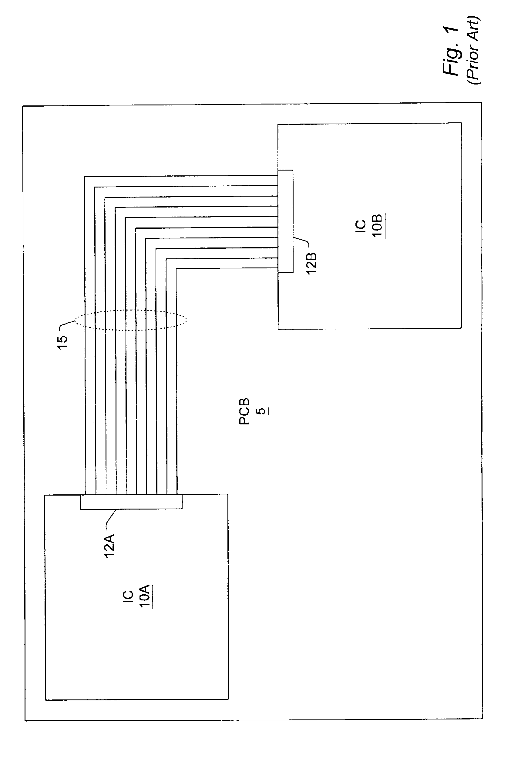
BACKGROUND OF THE INVENTION[0001]1. Field of the Invention[0002]This invention relates to electronic systems, and more particularly, the optimization and margin characterization of input / output lines.[0003]2. Description of the Related Art[0004]In the design and operation of high-speed digital systems, such as computer systems, skew occurring on signal lines is one important consideration. Skew may be defined as timing differences between signals due to various propagation delays. In order for data to be received at the correct value, it must be latched into a receiver at a certain time, at a certain voltage level. One timing difference of critical importance in digital systems is the timing difference that may exist between clock signals and data signals. These timing differences may occur for a number of reasons, such as varying signal line lengths, electrical characteristics of individual signal lines, and so on.[0005]FIG. 1 is a drawing of an exemplary printed circuit board (PCB...

Claims


Application Information

Patent Timeline
IPC IPC(8): G06F13/42G06F1/10G06K5/00G06K5/04H04L25/03H04L25/02G06F11/24G06F13/00H02H1/00H02H3/38H02H7/26
CPCG06F11/24H02H1/00H02H7/267H02H3/385G06F13/00
Inventor SMITH, BRIAN L.WU, JUEJONG, JYH-MINGFONG, WAIYUAN, LEOCHAKRABARTI, PRABHANSU
Owner ORACLE INT CORP
Learn More