
Delay-compensated fractional-N frequency synthesizer

a fractional-n frequency and delay-compensated technology, applied in the direction of pulse automatic control, electric devices, etc., can solve the problems of noise introduction, higher cost, and toggling, and achieve the effect of removing the noise introduced

Active Publication Date: 2005-09-13
PROTON WORLD INT
View PDF12 Cites 36 Cited by
  • Summary
  • Abstract
  • Description
  • Claims
  • Application Information

AI Technical Summary

Benefits of technology

[0008]In view of these drawbacks, it is an object of the present invention to overcome the above-mentioned drawbacks and to provide a device that synthesizes a fractional-N frequency based on a Phase-Locked Loop, in which the loop filter does not have to carry out strong filtering to remove the noise introduced by the fractional-N division operation.

Problems solved by technology

This toggling however introduces noise, which can be compared to the quantization noise in an Analog-to-Digital converter (ADC).
As these filters are too big to be integrated on chip, they are implemented as external components, resulting in higher cost.

Method used


Image

  • Delay-compensated fractional-N frequency synthesizer
  • Delay-compensated fractional-N frequency synthesizer
  • Delay-compensated fractional-N frequency synthesizer

Examples


Embodiment Construction

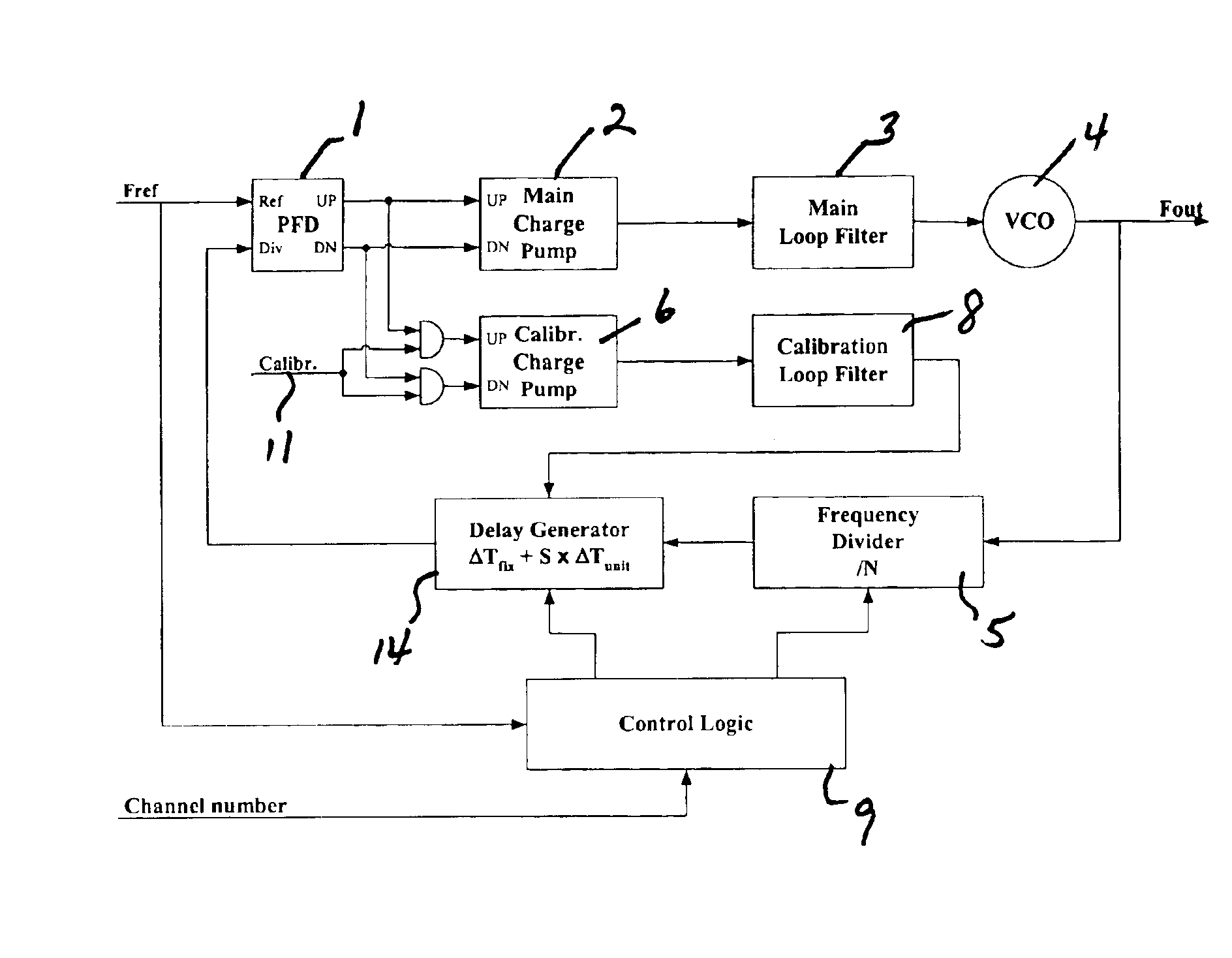
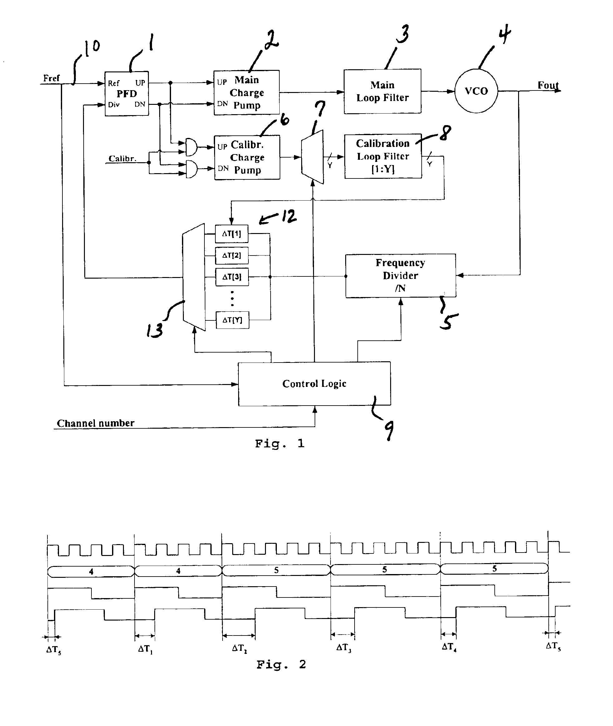
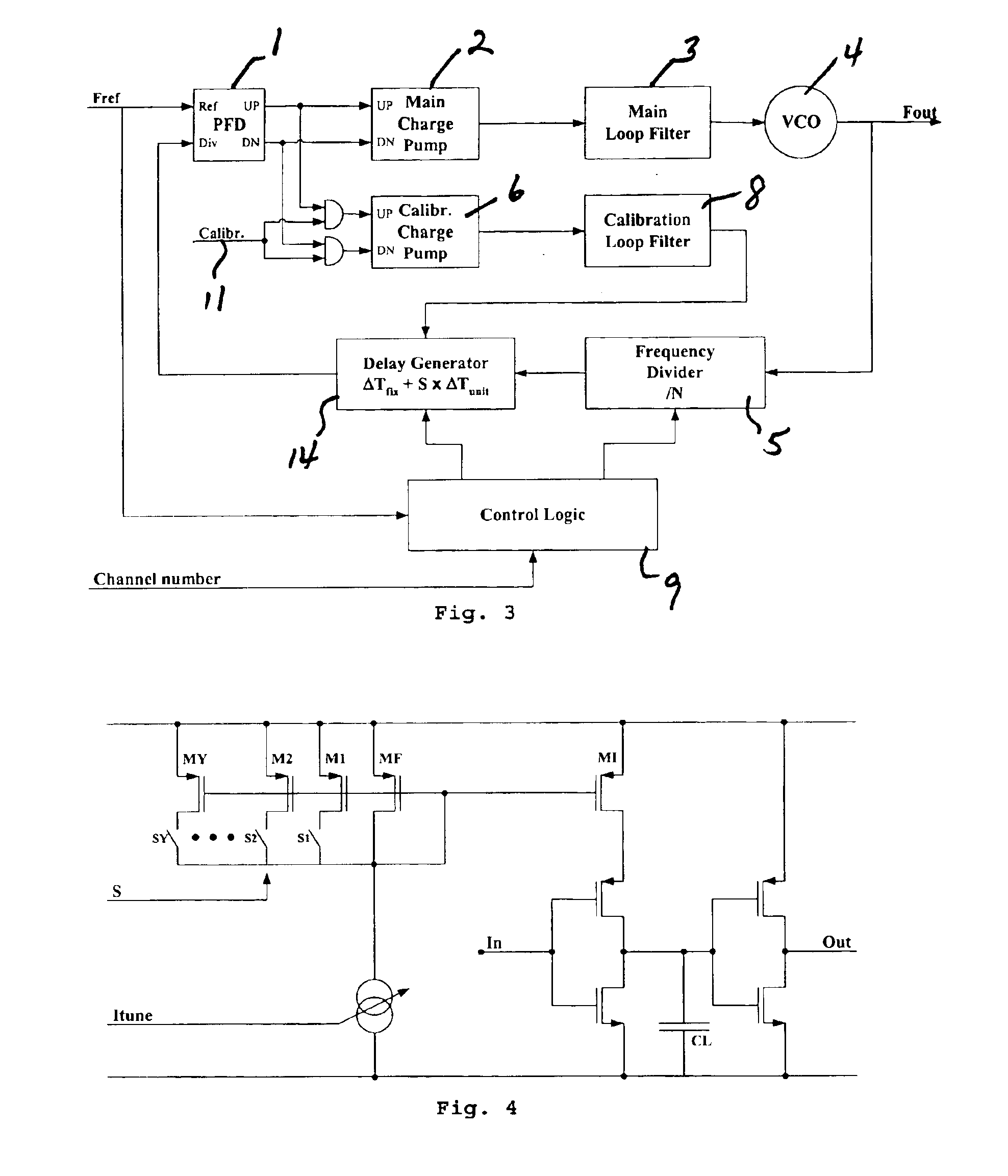
[0020]The basic principle applied in embodiments of the present invention is that the fractional ‘quantization’ noise is not shaped to higher frequencies, but cancelled out before it enters the Phase-Frequency Detector (PFD). In that way the loop filter does not have to filter it and the consequences on the PLL bandwidth are gone. The preferred implementation of this noise cancellation is based on delay cells added after the Frequency Divider.

[0021]An intermediate step toward the present invention is presented in FIG. 1. As shown, a main loop comprises, coupled in cascade, a Phase Frequency Detector (PFD) 1, a Main Charge Pump 2, a Main Loop Filter 3, a Voltage Controlled Oscillator (VCO) 4 and a Frequency Divider 5. A case in which a frequency

Fout=(N+X / Y)×Fref

must be synthesized, where N, X, and Y are integers, will now be described. The number n=N+X / Y is passed to the control block 9, which generates a sequence of division ratios. This sequence consists of X times the ratio N+1, a...


PUM


Abstract

A Phase-Locked Loop is provided that includes a main loop, a calibration loop, and Control Logic. The main loop comprises, coupled in series, a Phase Frequency Detector, a Main Charge Pump, a Main Loop Filter, a Voltage Controlled Oscillator and a Frequency Divider. The calibration loop is coupled to the Phase Frequency Detector and comprises a Calibration Charge Pump and a Calibration Loop Filter. The Control Logic controls the Frequency Divider and receives a control input signal. A Reference Frequency Signal is coupled to the Phase Frequency Detector and the Control Logic, and a calibration signal is coupled to the calibration loop. Additionally, the main loop further comprises a delay generator controlled by the Control Logic and arranged to receive correction signals from the calibration loop and to send an output signal to the Phase Frequency Detector.

Description

CROSS-REFERENCE TO RELATED APPLICATIONS[0001]This application is based upon and claims priority from European Patent Application No. 02-447268.0, filed Dec. 23, 2002, the entire disclosure of which is herein incorporated by reference.FIELD OF THE INVENTION[0002]The present invention is related to a fractional-N frequency synthesizer based on a Phase-Locked Loop, commonly used in digital communication systems.BACKGROUND OF THE INVENTION[0003]The generation of the Local Oscillator (LO) carriers used in radio transceivers is usually done with a phase-locked loop (PLL). With this circuit, an output frequency can only be an integer multiple of a reference frequency (Fout=N×Fref), which implies this reference frequency cannot be higher than the channel spacing. This limits the PLL bandwidth to approximately one tenth of the channel spacing, which implies settling times are sometimes too long.[0004]Also, the required frequency resolution sometimes is just too small to synthesize it as an i...

Claims


Application Information

Patent Timeline
IPC IPC(8): H03L7/08H03L7/089H03L7/197H03L7/081H03L7/16
CPCH03L7/081H03L7/0893H03L7/1976
Inventor CRANINCKX, JAN FRANS LUCIEN
Owner PROTON WORLD INT
Learn More