
Methods, systems and computer program products for failure recovery for routed virtual internet protocol addresses

a virtual internet protocol and failure recovery technology, applied in the field of network communications, can solve the problems of affecting the service life of the server, and affecting the reliability of the network, so as to reduce the disruption of the associated cluster of data processing systems

Inactive Publication Date: 2005-09-06
IBM CORP
View PDF66 Cites 76 Cited by
  • Summary
  • Abstract
  • Description
  • Claims
  • Application Information

AI Technical Summary

Benefits of technology

[0024]In yet other embodiments of the present invention, an identification of communication protocol stacks which are associated with the VIPA and the at least one port is defined at the backup routing communication protocol stack so as to provide a backup list of candidate target stacks which is different from the candidate target stacks of the primary routing communication protocol stacks. In such embodiments, the backup routing communication protocol may store the identification of communication protocol stacks associated with the VIPA and the at least one port as candidate target stacks by storing the backup list of candidate target stacks. In particular embodiments, the communication protocol stacks identified in the backup list of candidate target stacks are selected to reduce disruption of the cluster of data processing systems associated with the communication protocol stacks by failure of the primary routing communication protocol stack.
[0028]In further embodiments, the second set of candidate target communication protocol stacks are selected to reduce disruption of a cluster of data processing systems associated with the communication protocol stacks by failure of the primary routing communication protocol stack.

Problems solved by technology

If the failure is on a client workstation host, only the relatively few client connections are disrupted, and usually only one person is inconvenienced.
However, an adapter failure on a server means that hundreds or thousands of connections may be disrupted.
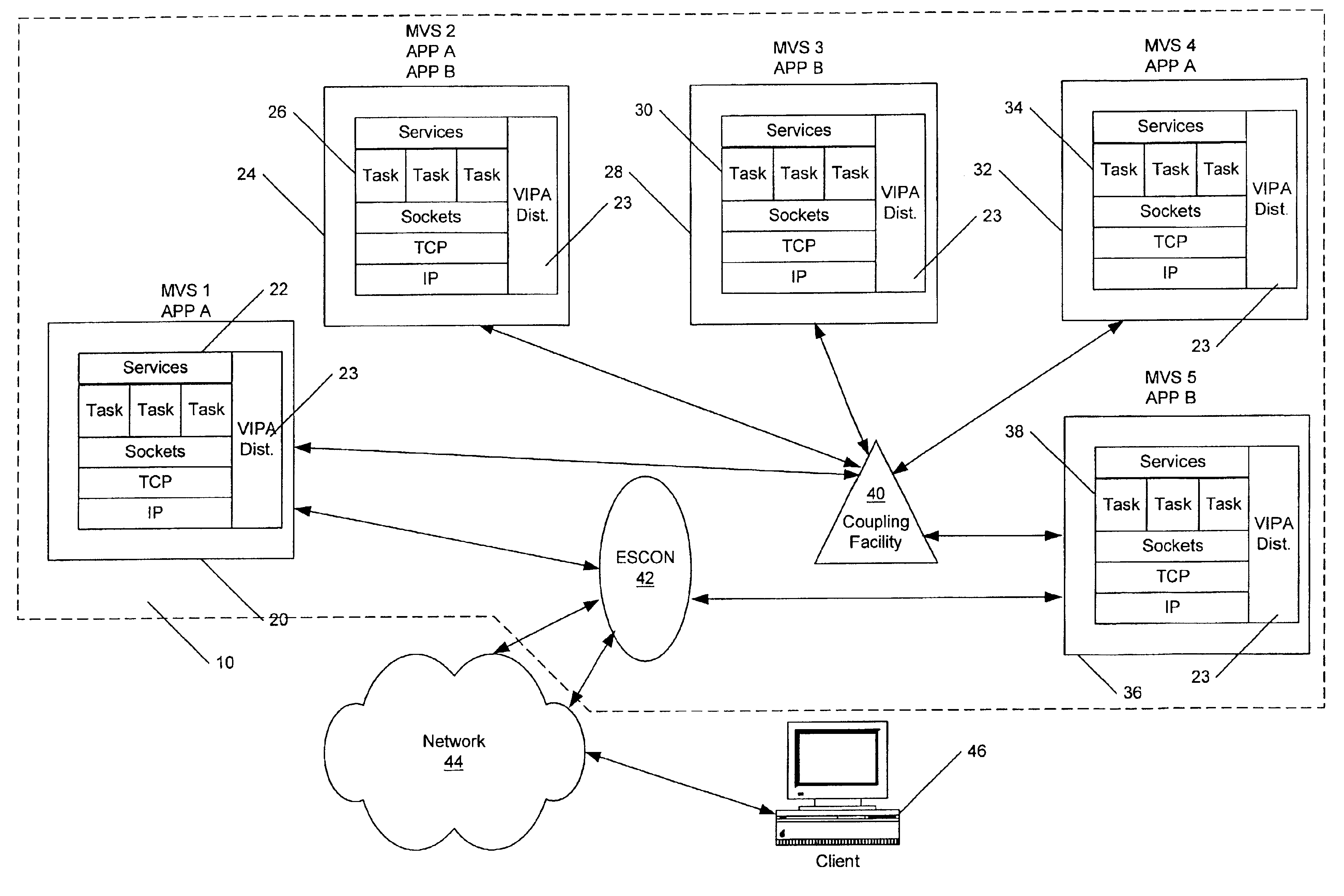
While the use of VIPAs may remove hardware and associated transmission media as a single point of failure for large numbers of connections, the connectivity of a server can still be lost through a failure of a single stack or an MVS image.
Substantial down time of a failed MVS image or TCP / IP stack may still result until operator intervention to manually reconfigure the TCP / IP stacks in a Sysplex to route around the failed TCP / IP stack or MVS image.
While merely restarting an application with a new IP address may resolve many failures, applications use IP addresses in different ways and, therefore, such a solution may be inappropriate.
However, in practice, things do not always work as described above.
However, the person using the client may not have the knowledge to reconfigure the client for a new IP address.
However, as described above, to affect such a movement of VIPAs between TCP / IP stacks requires operator intervention and may result in lengthy down times for the applications associated with the VIPA.
This may be acceptable when the application can be restarted in place, but is less useful when the application is moved to another node, unless the IP address known to the clients can be moved with the application, or dynamic DNS updates with alternate IP addresses can be propagated to a DNS local to clients sufficiently quickly.
In addition to failure scenarios, scalability and load balancing are also issues which have received considerable attention in light of the expansion of the Internet.
The node performing the distribution function connects to the endpoint stack via a single hop connection because normal routing protocols typically cannot be used to get a connection request from the endpoint to the distributing node if the endpoint uses the same IP address as the distributing node advertises.

Method used


Image

  • Methods, systems and computer program products for failure recovery for routed virtual internet protocol addresses
  • Methods, systems and computer program products for failure recovery for routed virtual internet protocol addresses
  • Methods, systems and computer program products for failure recovery for routed virtual internet protocol addresses

Examples


Embodiment Construction

[0044]The present invention now will be described more fully hereinafter with reference to the accompanying drawings, in which preferred embodiments of the invention are shown. This invention may, however, be embodied in many different forms and should not be construed as limited to the embodiments set forth herein; rather, these embodiments are provided so that this disclosure will be thorough and complete, and will fully convey the scope of the invention to those skilled in the art. Like numbers refer to like elements throughout.

[0045]As will be appreciated by those of skill in the art, the present invention can take the form of an entirely hardware embodiment, an entirely software (including firmware, resident software, micro-code, etc.) embodiment, or an embodiment containing both software and hardware aspects. Furthermore, the present invention can take the form of a computer program product on a computer-usable or computer-readable storage medium having computer-usable or comp...


PUM


Abstract

Methods, systems and computer program products provide for recovery from a failure of a primary routing communication protocol stack which routes communications over connections to a virtual Internet Protocol address (VIPA) and at least one port associated with the VIPA to a plurality of other communication protocol stacks associated by the primary routing stack and with the VIPA and the at least one port. At least one backup routing communication protocol stack is identified. The backup routing stack stores an identification of stacks associated with the VIPA and the at least one port as candidate target stacks. Messages are received at the backup routing stack identifying stacks having application instances bound to the VIPA and listening on the at least one port as current actual target stacks. Connections to the VIPA and the at least one port for current actual target stacks are also identified and a routing table constructed from the received messages so as to provide routing path information to current actual target stacks associated with the connection. Messages on the connections to the VIPA and the at least one port are routed through the backup stack utilizing the constructed routing table.

Description

RELATED APPLICATIONS[0001]The present application is related to concurrently filed and commonly assigned Unites States patent application Serial No. 09 / 640,412 entitled “METHODS, SYSTEMS AND COMPUTER PROGRAM PRODUCTS FOR NON-DISRUPTIVELY TRANSFERRING A VIRTUAL INTERNET PROTOCOL ADDRESS BETWEEN COMMUNICATION PROTOCOL STACKS” and U.S. patent application Ser. No. 09 / 640,409, entitled “METHODS, SYSTEMS AND COMPUTER PROGRAM PRODUCTS FOR FAILURE RECOVERY FOR CLUSTER WORKLOAD DISTRIBUTION”, the disclosures of which are incorporated herein by reference as if set forth fully herein.FIELD OF THE INVENTION[0002]The present invention relates to network communications and more particularly to network communications to a cluster of data processing systems.BACKGROUND OF THE INVENTION[0003]The Internet Protocol (IP) is a connectionless protocol. IP packets are routed from originator through a network of routers to the destination. All physical adapter devices in such a network, including those for ...

Claims


Application Information

Patent Timeline
IPC IPC(8): G06F11/00G06F15/16H04L12/56
CPCG06F11/203H04L45/00H04L45/586G06F11/2035
Inventor AIKEN, JR., JOHN ANDREWCHRISTENSEN, ALFRED BUNDGAARDDEVINE, WESLEY MCMILLANHERR, DAVID ANTHONYMCCLINTOCK, MARK W.
Owner IBM CORP
Learn More