
Method, apparatus and computer program product for determination of noise in mixed signal systems

a mixed signal and noise technology, applied in the direction of electric/magnetic computing, instruments, analogue processes for specific applications, etc., can solve the problems of spice not being able to be used economically to simulate the noise coupling of substrates, the simulation time and memory requirements are too high, and the performance of analog circuits are degraded. , to achieve the effect of fast and accurate noise determination

Inactive Publication Date: 2005-09-06
INTERUNIVERSITAIR MICRO ELECTRONICS CENT (IMEC VZW)
View PDF13 Cites 198 Cited by
  • Summary
  • Abstract
  • Description
  • Claims
  • Application Information

AI Technical Summary

Benefits of technology

[0015]The invention aims at presenting methods and apparatus adapted for fast and accurate determination of noise in mixed signal systems, such systems comprising at least a digital system part and at least an analog system part. The digital system may be the dominant part. Said invention is of importance in single chip integration where signal integrity analysis is vital.

Problems solved by technology

These mixed-signal ICs require careful analysis of the interaction between the digital and analog part: the digital part will create noise particularly from switching actions and the leading and trailing edges of digital signals, which will degrade the performance of the analog circuits.
But for large digital circuits (with, for example, millions of transistors) SPICE can no longer be used economically to simulate the substrate noise coupling: the simulation time and memory requirement are too high.
The impact analyzing methods are in particular very important in mixed type designs wherein the possibilities for influence limiting approaches are less easy applicable.
Such transistor-level simulation however becomes extremely hard to perform for large digital systems with lots of gates.
Also noise coupling from the power supply is not taken into account.
This signal is however only a rough estimate and not an accurate waveform of the noise signal, as it is based on said mathematical noise signal of a predetermined or fixed shape.
Gate dependency can not be accurately be modeled.
They assume that the noise coupling from the on-chip power supply is the dominant source of substrate noise.

Method used


Image

  • Method, apparatus and computer program product for determination of noise in mixed signal systems
  • Method, apparatus and computer program product for determination of noise in mixed signal systems
  • Method, apparatus and computer program product for determination of noise in mixed signal systems

Examples


Embodiment Construction

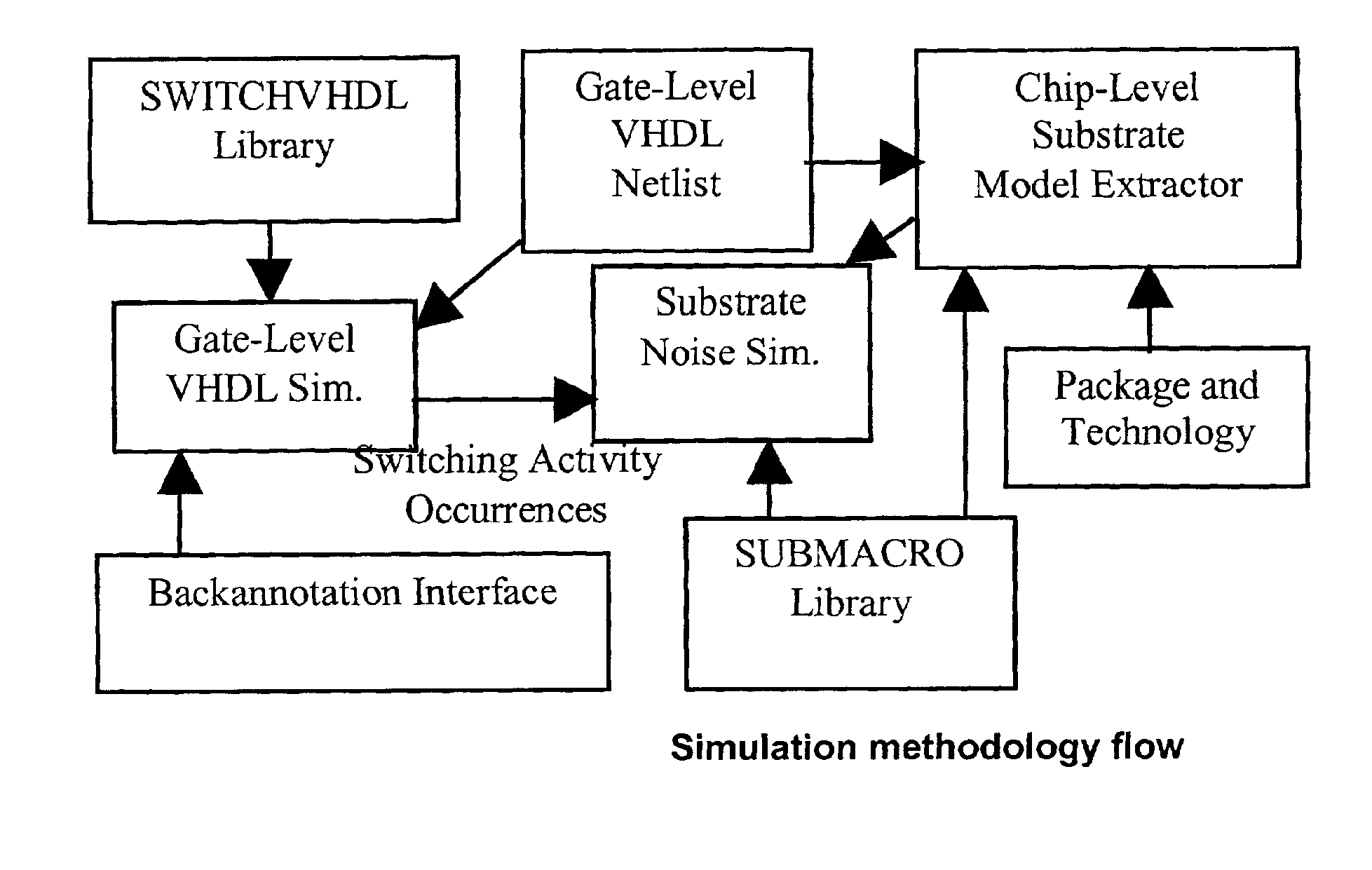
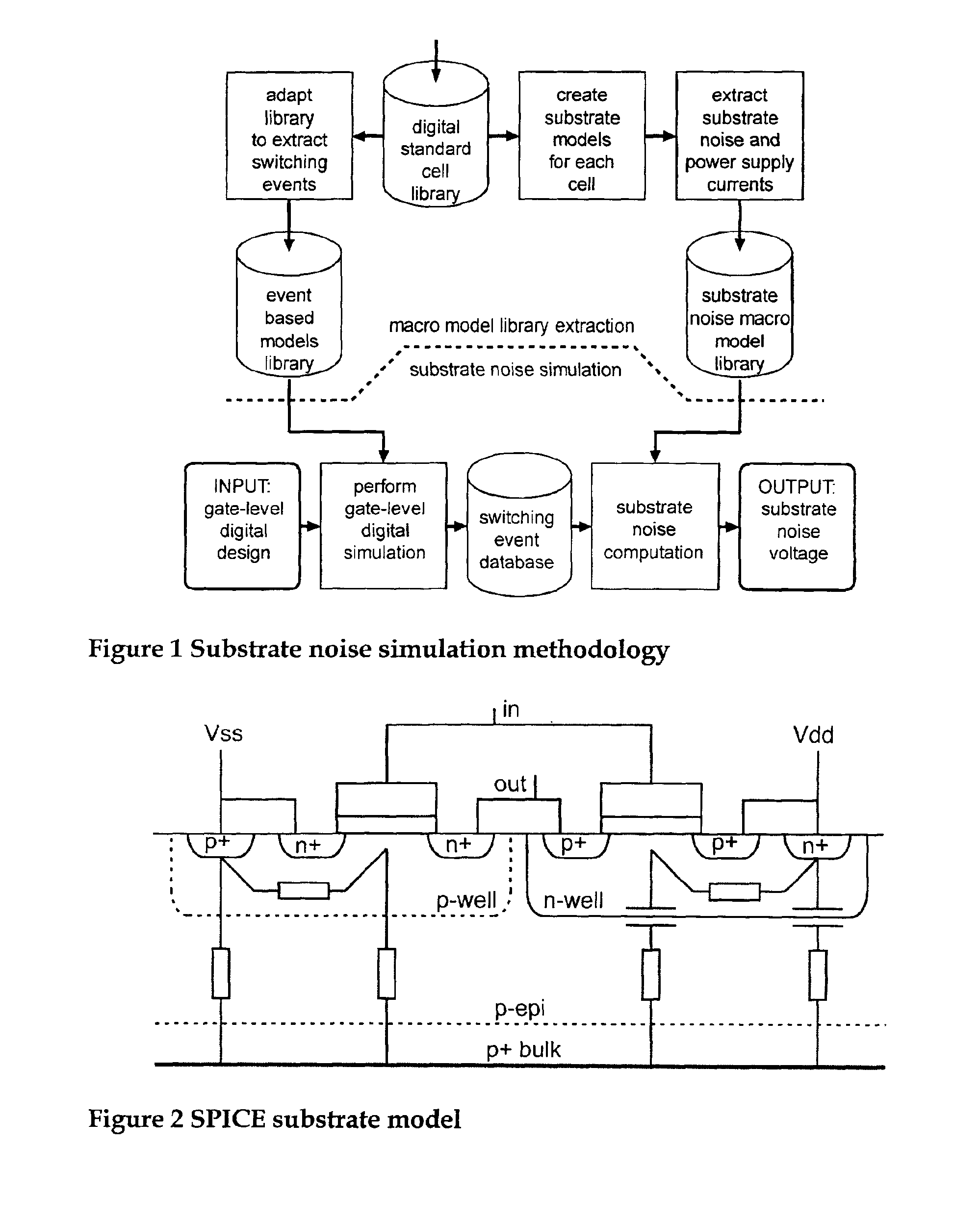
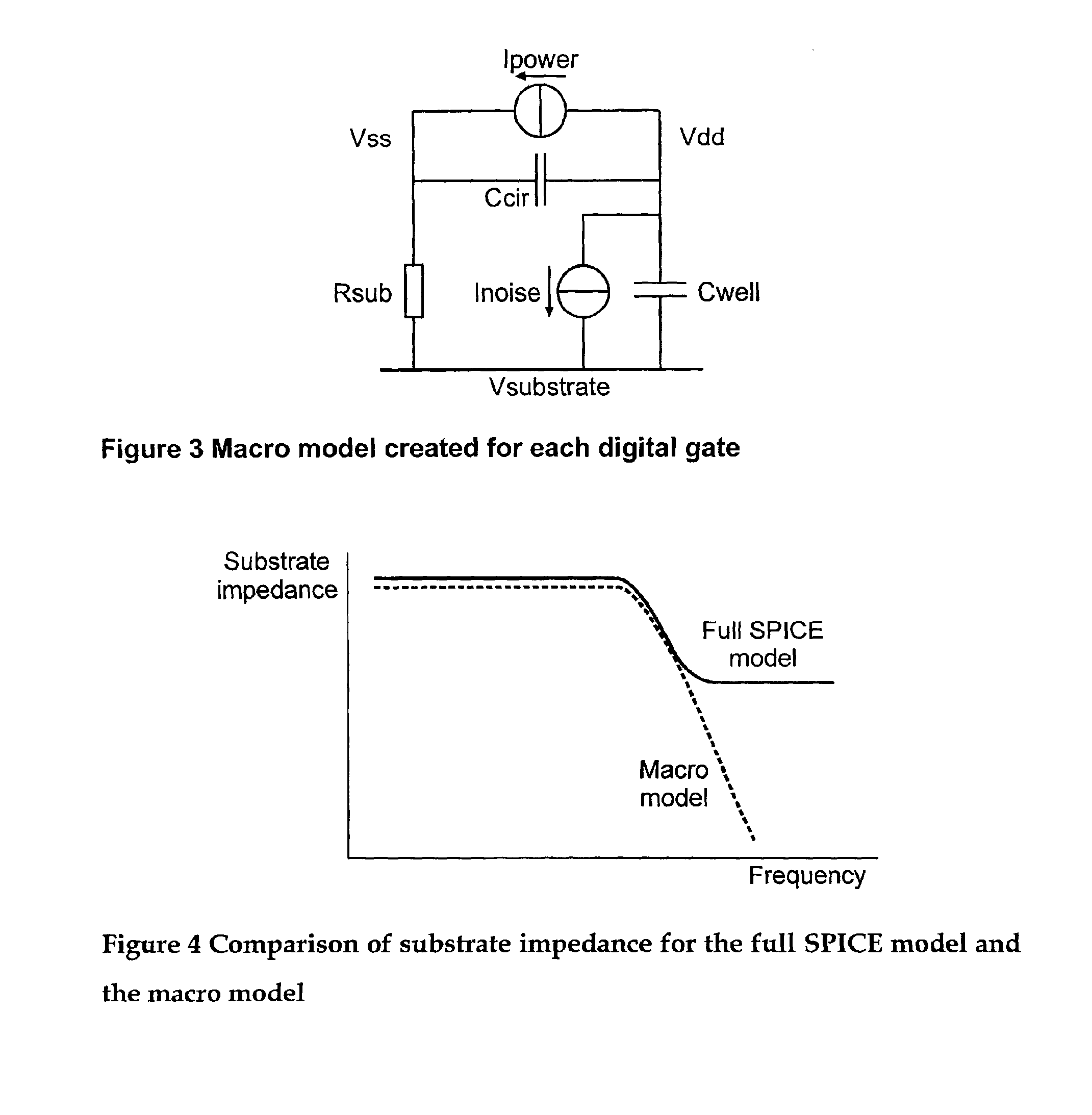
[0077]The present invention will be described with reference to certain embodiments and drawings but is not limited thereto but only by the claims. The invention focuses on methods for determining the noise generated by a digital circuit with at least one gate, formed on a substrate, e.g. a semiconductor substrate. Where reference is made to “gate” it should be appreciated that a grouping of gates is included within the meaning of this term. The substrate may be high-ohmic (e.g. highly resistive) or low-ohmic. In the following reference will be made to computer programs and languages such as SPICE or VHDL. These are given only as examples and the invention is not limited thereto. For instance, instead of SPICE any other suitable transistor level simulation could be used, e.g. from MatLab. Instead of VHDL another suitable register transfer level description could be used, e.g. VERILOG.

[0078]Said methods are useful for the evaluation of the effect of said generated noise on an analog ...


PUM


Abstract

A simulation system is described for computing the overall signal generated in a substrate by a digital system comprising a plurality of gates associated with the substrate, wherein each gate is configured to perform a switching event. Output of a transistor-level model is compared with output of a lumped circuit model for each gate and the substrate, and signal contributions from each gate and switching event are determined based on the comparison. The system determines switching event signals for each of the plurality of gates. The signal contributions and the switching event signals are combined, and a combined lumped circuit model is derived based on a combination of lumped circuit models of the plurality of gates. The overall signal is computed based on the combined gate signal contributions and switching event signals, which are configured as an input to the combined lumped circuit model.

Description

[0001]This application claims the benefit of the U.S. Provisional Applications Ser. No. 60 / 190,704, filed Mar. 17, 2000 and Ser. No. 60 / 266,184, filed Feb. 2, 2001.[0002]The invention relates to analysis of the noise coupling problem in mixed signal systems and more in particular to methods for determining noise in said mixed signal systems and to an apparatus implementing said methods. The methods may be implemented using a computer program product such as an executable program stored on a suitable data carrier, executable for example, on a computer system.BACKGROUND OF THE INVENTION[0003]The need to integrate as much functionality on one integrated circuit (IC), has led to the development of more and more mixed-signal ICs, comprising at least one digital circuit and at least one analog circuit. These ICs usually contain a large digital circuit, together with a small analog circuit. For example, an analog-to-digital converter can be integrated together with a baseband digital signa...

Claims


Application Information

Patent Timeline
Patent Type & Authority Patents(United States)
IPC IPC(8): G01R31/3167G06F17/50
CPCG01R31/3167G06F30/367G06F30/33
Inventor VAN HEIJNINGEN, MARCBADAROGLU, MUSTAFA
Owner INTERUNIVERSITAIR MICRO ELECTRONICS CENT (IMEC VZW)
Learn More