
On-chip interface trap characterization and monitoring

a technology of interface traps and on-chip interfaces, applied in error detection/correction, power supply testing, instruments, etc., can solve the problems of high cost and time-consuming setup of waveform generators, noise in integrated circuit devices,

Active Publication Date: 2008-12-30
INTEGRATED DEVICE TECH INC
View PDF17 Cites 13 Cited by
  • Summary
  • Abstract
  • Description
  • Claims
  • Application Information

AI Technical Summary

Benefits of technology

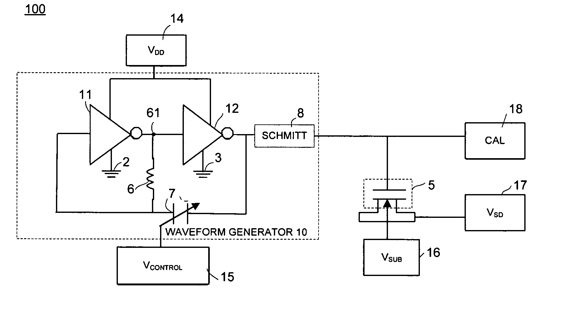
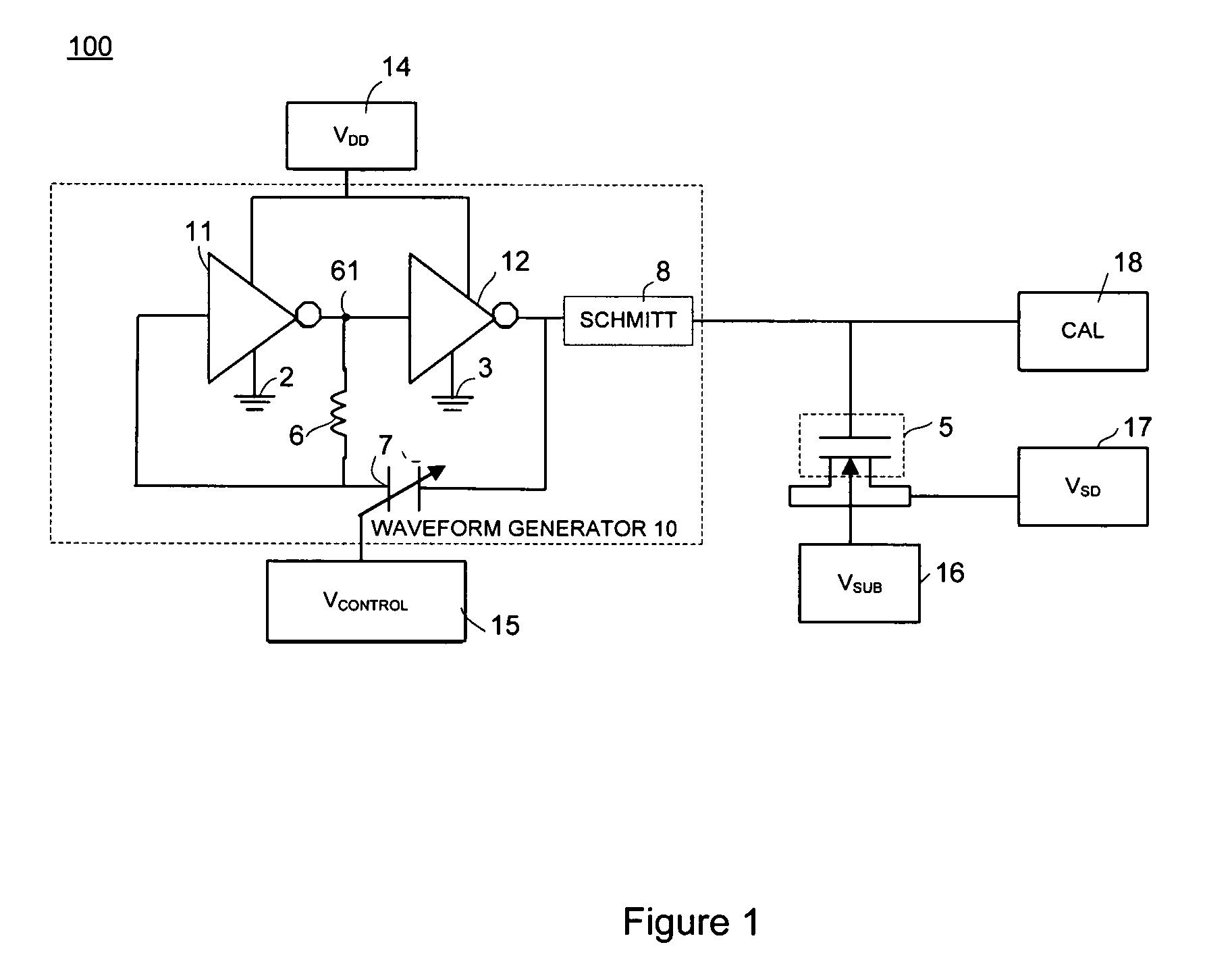
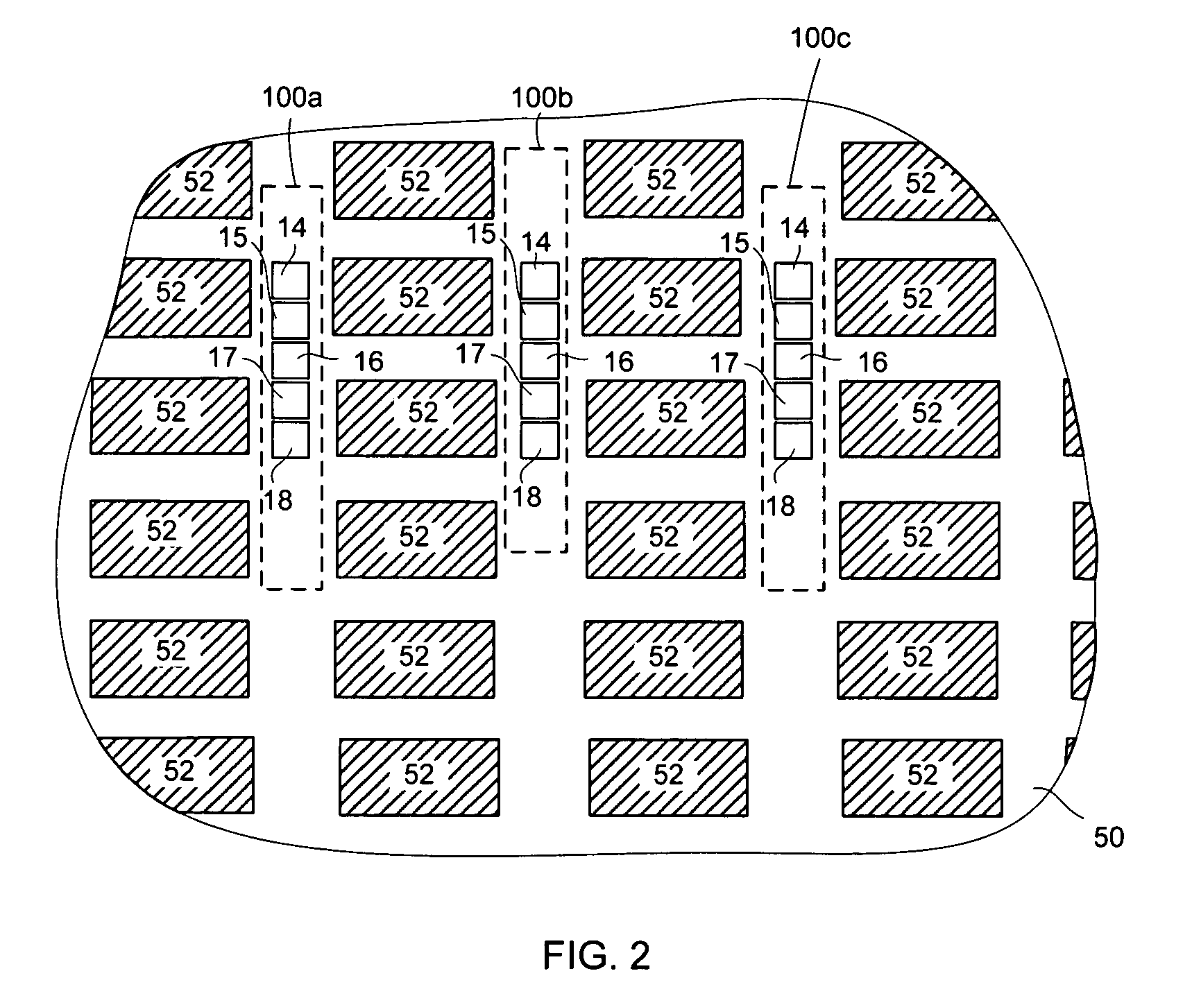
[0005]The present invention provides a method and apparatus for testing semiconductor wafers using a test circuit that includes a waveform generator. In one embodiment, each test circuit includes a waveform generator and a single device under test. In another embodiment multiple devices under test are connected to a common set of contact pads, allowing for testing of multiple different devices on the semiconductor wafer using a limited number of contact pads.
[0007]Accordingly, the method and apparatus of the present invention facilitates in-line automatic measurement of interface state density, allowing for quick and accurate determination of interface state density. Moreover, because the test circuits of the present invention include a waveform generator, there is no need to connect the test circuitry to a stand-alone waveform generator as is required in prior art testing methods, saving setup time and the cost of purchasing a stand-alone waveform generator. These and other advantages of the present invention will no doubt become obvious to those of ordinary skill in the art after having read the following detailed description of the preferred embodiments, which are illustrated in the various drawing figures.

Problems solved by technology

It is believed that 1 / f noise in integrated circuit devices is caused by charge trapping and de-trapping at the traps near the oxide and silicon interface.
However, the waveform generator is expensive and time consuming to set up.

Method used


Image

  • On-chip interface trap characterization and monitoring
  • On-chip interface trap characterization and monitoring
  • On-chip interface trap characterization and monitoring

Examples


Embodiment Construction

[0018]Reference will now be made in detail to the preferred embodiments of the invention, examples of which are illustrated in the accompanying drawings. While the invention will be described in conjunction with the preferred embodiments, it will be understood that they are not intended to limit the invention to these embodiments. On the contrary, the invention is intended to cover alternatives, modifications and equivalents, which may be included within the spirit and scope of the invention as defined by the appended claims. Furthermore, in the following detailed description of the present invention, numerous specific details are set forth in order to provide a thorough understanding of the present invention. However, it will be obvious to one of ordinary skill in the art that the present invention may be practiced without these specific details. In other instances, well-known methods, procedures, components, and circuits have not been described in detail so as not to unnecessarily...


PUM


Abstract

A method and apparatus for testing semiconductor wafers is disclosed in which a test circuit is used that includes a waveform generator. The test circuit can test a single transistor or can test multiple transistors. A testing method is disclosed in which a supply voltage is applied to the waveform generator to produce pulses that are applied to the gate of a transistor to be tested. A bias voltage is applied to the source and drain of the transistor to be tested, and the charge pumping current that is generated at the substrate is then measured. The process can be repeated at different bias voltage levels to obtain additional current measurements, indicating the maximum charge pumping current for the transistor that is being tested. The determined maximum charge pumping current can then be used for determining whether there is excessive 1 / f noise in the device under test.

Description

FIELD OF THE INVENTION[0001]The present invention relates to the field of semiconductor devices. More specifically, the present invention relates to semiconductor device testing circuitry and methods for testing semiconductor devices.BACKGROUND ART[0002]1 / f noise is important in mixed signal and analog application because it presents a lower limit of the signal level that can be processed. It is believed that 1 / f noise in integrated circuit devices is caused by charge trapping and de-trapping at the traps near the oxide and silicon interface. One conventional process for characterizing the density of interface traps includes connecting a stand-alone waveform generator to the semiconductor substrate and connecting a testing device to the waveform generator. Typically, the testing device is a computer that connects to the waveform generator using an electrical cable that connects to a serial port or a USB port on the waveform generator. However, the waveform generator is expensive and...

Claims


Application Information

Patent Timeline
Patent Type & Authority Patents(United States)
IPC IPC(8): G01R31/317G01R31/40
CPCG01R31/2621G01R31/2839G01R31/2884G01R31/318511
Inventor MA, ZHIJIANLIU, CHUNBO
Owner INTEGRATED DEVICE TECH INC
Learn More