Information processing apparatus, mode control method and storage medium

Inactive Publication Date: 2005-08-30
FUJITSU LTD
View PDF12 Cites 11 Cited by
  • Summary
  • Abstract
  • Description
  • Claims
  • Application Information

AI Technical Summary

Benefits of technology

[0008]Accordingly, it is a general object of the present invention to provide a novel and useful information processing apparatus, mode control method and storage medium, in which the problems described above are eliminated.
[0010]Still another object of the present invention is to provide an information processing apparatus having a power save mode, comprising a spool storing print data, and control means for monitoring a state of the spool and for prohibiting a transition to the power save mode in a state where the print data is stored in the spool. According to the information processing apparatus of the present invention, it is possible to quickly make a transition to the power save mode regardless of an operating state of a printer which is coupled to the information processing apparatus, when it becomes possible for the information processing apparatus to make the transition to the power save mode.

Problems solved by technology

On the other hand, the problems described above also occur when the information processing apparatus makes a transition to a power OFF state.
However, the proposed apparatus and the proposed method described above basically prohibit the transition to the power save mode or the power OFF state during the operation of the printer.
Thus, even if all the data within the spool have been transferred to the printer and the information processing apparatus may make the transition to the power save mode or the power OFF state, there was a problem in that the transition to the power save mode or the power OFF state is prohibited while the printer is operating.
For this reason, in cases where a large amount of data is to be printed on the printer, a print speed of the printer is slow and the like, the printer continues to operate for a long time, thereby putting the information processing apparatus in a wait state for a long time.

Method used


Image

  • Information processing apparatus, mode control method and storage medium
  • Information processing apparatus, mode control method and storage medium
  • Information processing apparatus, mode control method and storage medium

Examples


first embodiment

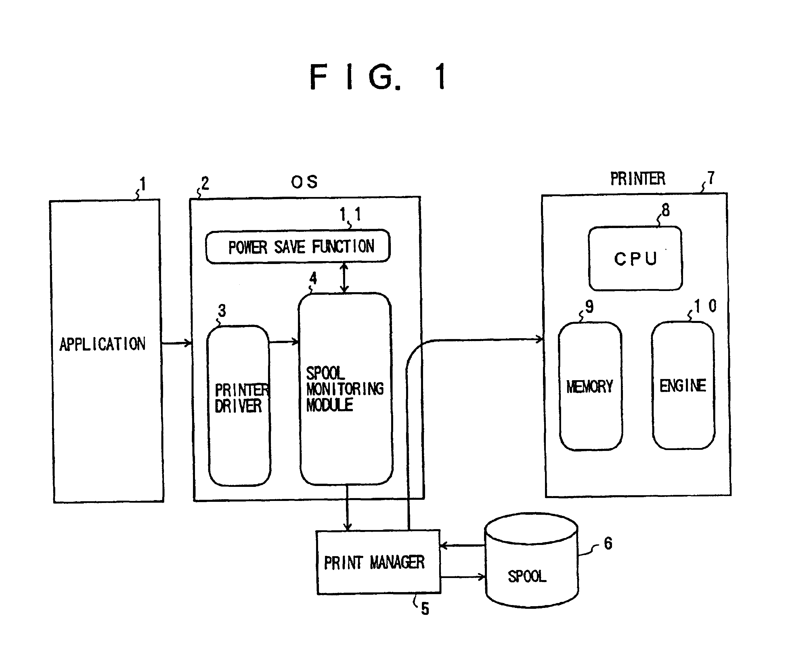
[0031]The program which realizes the above described functions of the spool monitoring module 4 within the OS 2 is stored in the storage medium.

[0032]FIG. 2 is a system block diagram generally showing the hardware construction of this embodiment. In FIG. 2, those parts which are the same as those corresponding parts in FIG. 1 are designated by the same reference numerals, and a description thereof will be omitted. A personal computer 100 includes a CPU 101, memories 102 and 103, an input device 104 made up of a keyboard, for example, a display unit 105, and a bus 106 which couples these elements of the personal computer 100. For example, the memory 102 stores the application 1 executed by the CPU 101, the OS 2 and the print manager 5. On the other hand, the memory 103 includes a region for storing the contents of the spool 6, a region for storing intermediate data of computation processes carried out by the CPU 101, and the like. These memories 102 and 103 are not limited to a speci...

second embodiment

[0039]FIG. 4 is a flow chart for explaining the process carried out by the CPU 101 of the personal computer 100 shown in FIG. 2 in this In FIG. 4, those steps which are the same as those corresponding steps in FIG. 3 are designated by the same reference numerals, and a description thereof will be omitted. In this embodiment, the spool monitoring module 4 is normally set to the enabled state.

[0040]In FIG. 4, a step S1a sets the personal computer 100 to the started state, and also sets the spool monitoring module 4 to the enabled state. A step S11 displays a message on the display unit 105 to indicate that the printer 7 carrying out a print operation, so as to urge the user to make an input instructing the enabled / disabled state of the spool monitoring module 4. In addition, a step S12 decides whether or not the disabled state of the spool monitoring module 4 is instructed by the user from the input device 104, and the process advances to the step S6 if the decision result in the ste...

third embodiment

[0045]FIG. 5 is a flow chart for explaining the process carried out by the CPU 101 of the personal computer 100 in this In FIG. 5, when the personal computer 100 assumes the power ON state, the step S1 starts the personal computer 100, and a step S32 decides whether or not the personal computer 100 is set to the power OFF state by the user. If the decision result in the step S32 is NO, the personal computer 100 is maintained to the started state. On the other hand, if the decision result in the step S32 becomes YES, the step S3 decides whether or not the printer 7 is carrying out a print operation. If the decision result in the step S3 is YES, the step S4 decides whether or not the print data is stored in the spool 6 within the memory 102. If the decision result in the step S4 is YES, a step S25 prohibits the transition of the personal computer 100 to the power OFF state by the power save function 11. In addition, the step S6 decides whether or not the print data is stored in the s...


PUM


Abstract

An information processing apparatus having a power save mode is constructed to include a spool storing print data, and a controller for monitoring a state of the spool and for prohibiting a transition to the power save mode in a state where the print data is stored in the spool.

Description

BACKGROUND OF THE INVENTION[0001]The present invention generally relates to information processing apparatuses, mode control methods and storage mediums, and more particularly to an information processing apparatus which processes print data to be printed on a printer, a mode control method which controls a mode of such an information processing apparatus, and a computer readable storage medium which stores a program for controlling such an information processing apparatus.[0002]In information processing apparatuses such as personal computers, a power save mode is provided to reduce the power consumption. Even in a state where the power is ON, if the information processing apparatus is not used, the power save mode puts various parts of the information processing apparatus to a state which is as close as possible to a power OFF state, so as to reduce the power consumption. In the power save mode, data exchanges among the various parts of the information processing apparatus are also...

Claims


Application Information

Patent Timeline
IPC IPC(8): G06F1/32G06F3/12B41J29/38G06F1/26
CPCG06F1/3215G06F3/12Y02B60/1271Y02D10/00
Inventor IIZUKA, JUNICHIHAYAKAWA, TASUKU
Owner FUJITSU LTD
Why Eureka
Try Eureka