
Method for the production of a valve

a production method and valve technology, applied in the field of valve production methods, can solve the problems of large amount of production rejection, difficult to precisely set the desired switching stroke, and relatively complex production of such valves, and achieve the effect of reliable valve production

Inactive Publication Date: 2005-08-16
FESTO AG & CO KG
View PDF13 Cites 35 Cited by
  • Summary
  • Abstract
  • Description
  • Claims
  • Application Information

AI Technical Summary

Benefits of technology

[0005]One object of the present invention is to provide a method which irrespectively of manufacturing inaccuracies renders possible simple and simultaneously reliable production of a valve.
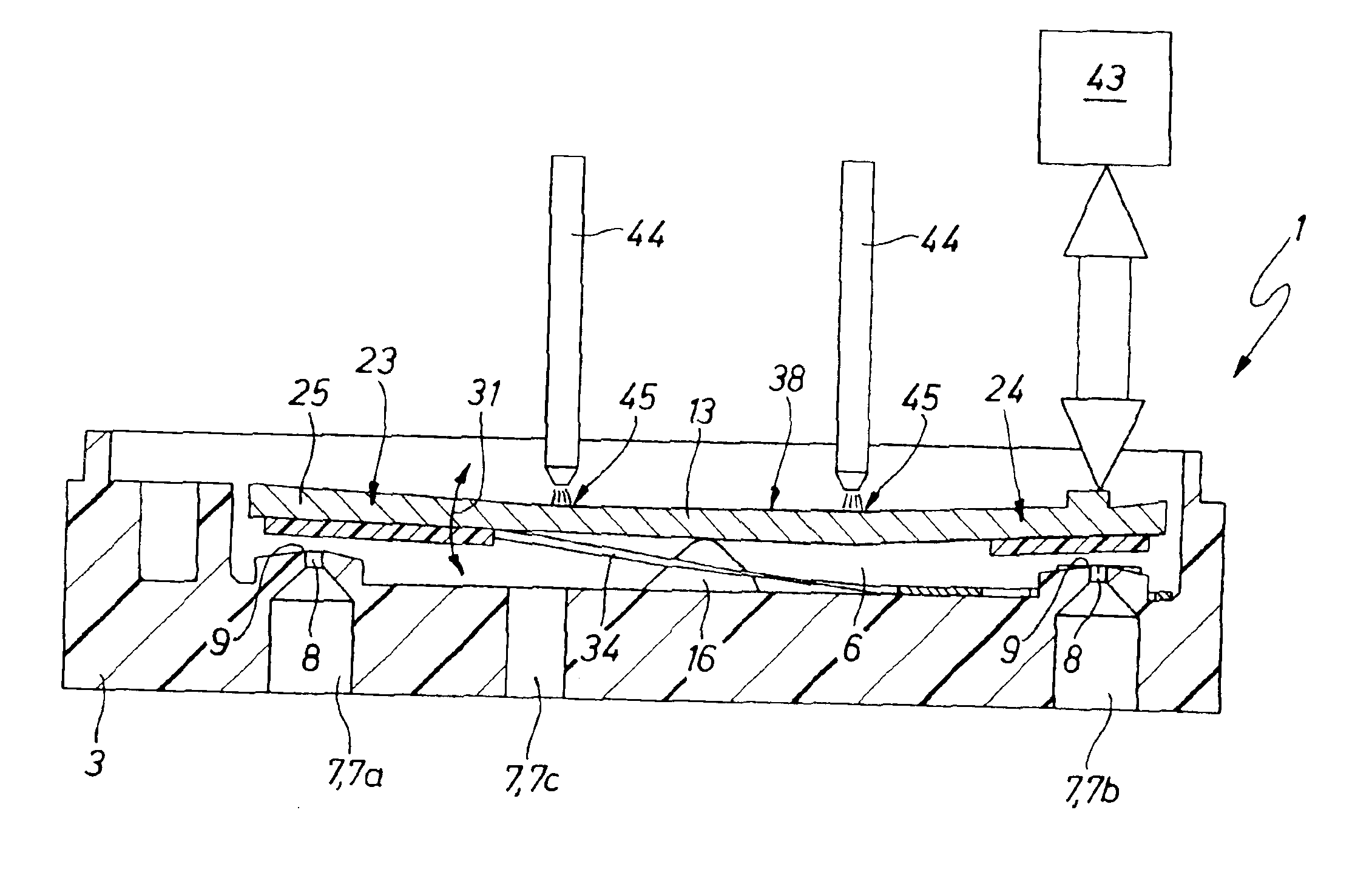
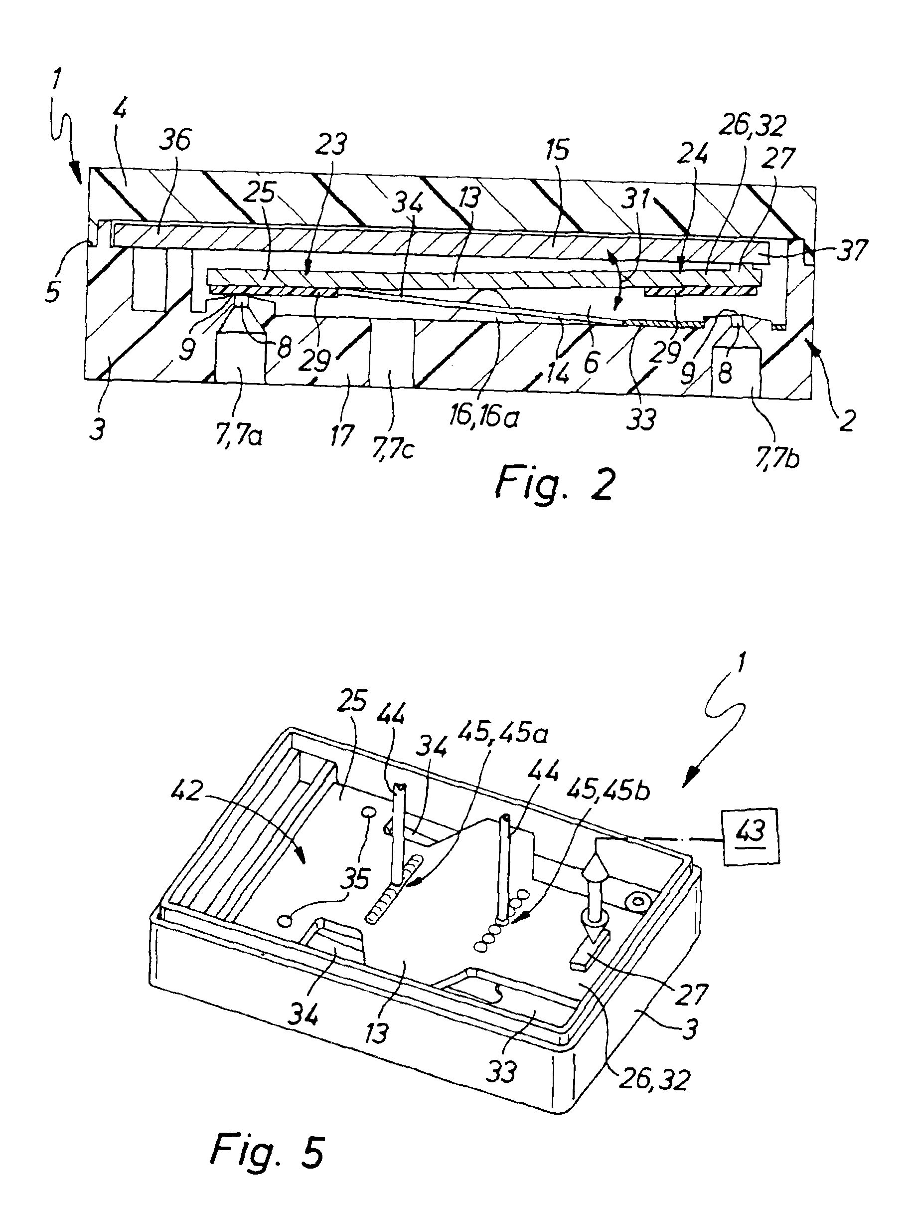
[0007]Owing to the brief, locally limited incipient fusion of the valve member at its surface it is possible to ensure that the valve member is slightly flexed in the eventual direction of pivoting and permanently dwells in a final condition which is curved out of the initial state. Since the deformation is performed without the application of an external flexing force, it prevents damage to the valve member. Owing to exact metering of the input of energy causing the heating, exact adjustment is possible even in the case of extremely small dimensions of the valve members. There is the possibility of causing a permanent deformation of the valve member by suitably checked input of energy so that its closure section in the closed position is exactly planar and accordingly rests reliably on the associated valve seat.
[0012]In the case of serial production of a major number of similar valves a slightly modified method is an advantage. In this case the process takes place in a closed loop control circuit. After flexural deformation of a valve member the difference then existing between the actual switching stroke and the intended switching stroke is measured, this being followed not by further possible deformation of the checked valve member but of the next one in the series. This member is then heated in a manner modified to take into account the stroke difference detected, for example by changing the thermal intensity, by changing the heating cycles or the areas heated so that the intended switching stroke is produced at least with a better degree of approximation. The result of deformation is then remeasured and utilized as a basis for any recorrected heating of the following valve or, respectively, valve member. The particular advantage of this laser loop adjustment in a closed loop control circuit is that the adjustment is performed continuously to follow up the varying housing dimensions. Moreover, adjustment and checking are decoupled from one another, this leading to shorter cycle times.

Problems solved by technology

Owing to the presence of manufacturing inaccuracies of the components the production of such valves is relatively complex.
More especially in the case of valves with very small dimensions and more particularly micro-valves, the manufacturing inaccuracies are very prone to have a size near the size of the switching stroke of the valve member so that it is extremely difficult to exactly set the desired switching stroke.
The result may be a considerable amount of production rejects.
Furthermore, this necessitates mechanically acting on the valve member by means of an external body providing the biasing force, something which more particularly in the case of very small and thin valve members may in certain circumstance lead to functional impairment.

Method used


Image

  • Method for the production of a valve
  • Method for the production of a valve
  • Method for the production of a valve

Examples


Embodiment Construction

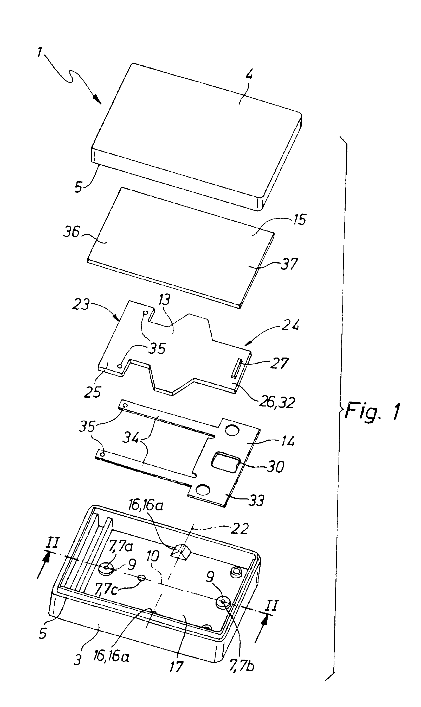
[0026]The valves 1 illustrated in drawing are more particularly suitable for the application of the method of the invention. However, the method may also be applied for valves with a different design.

[0027]Firstly there will be a description of a preferred structure of the valve 1 to be subjected to the method of the invention.

[0028]The valve 1 may have comparatively small dimensions so that it could be termed a micro-valve. More particularly in conjunction with valves with small and minimum dimensions advantageous application of the method is possible. However, it may be applied to valves of any dimensions.

[0029]The valve 1 has a housing 2, which in the working embodiment illustrated is composed of a housing bottom part 3 and a housing cover 4 secured to it in a sealing fashion. These two parts are preferably produced by injection molding, more especially using plastic material. The connection in the joint region 5 is preferably performed by laser welding or by bonding. In the inte...


PUM

PropertyMeasurementUnit
obtuse angleaaaaaaaaaa
flexural deformationaaaaaaaaaa
energyaaaaaaaaaa

Abstract

A method for the manufacture of a valve having at least one valve opening surrounded by at least one valve seat and an elongated valve member able to be brought into different positions by pivoting. In order to adjust the switching stroke of the valve member the valve member is, for instance using a laser, locally and briefly heated until superficial plastification occurs so that in the direction of the pivoting movement performed in operation it experiences a permanent flexural deformation.

Description

BACKGROUND OF THE INVENTION[0001]The invention relates to a method for the production of a valve, which comprises at least one valve opening surrounded by a valve seat and furthermore an elongated valve member able to be positioned by pivoting selectively into a closing position with a closure section resting on the at least one valve seat or into an open position clear of the valve seat.THE PRIOR ART[0002]For the control of fluid flows various different types of electrically operated valve are employed, which possess an elongated valve member, which is able to be switched over in a pivoting movement between different positions. The German patent publication 19,957,953 A1 describes such a valve in the case of which the valve member is constituted by piezoelectric flexural transducer which is held at one end thereof. The European patent publication 1158182 A1 describes a valve, which has a pivotally mounted rocker-like valve member and which by the action of a piezoelectric flexural ...

Claims


Application Information

Patent Timeline
Patent Type & Authority Patents(United States)
IPC IPC(8): F16K31/00
CPCF16K31/006Y10T29/49423Y10T137/86847Y10T137/86622Y10T137/0502
Inventor WEINMANN, MICHAELMUNZ, GEBHARDMAICHL, MARTINMUNZENMAIER, ANDREAS
Owner FESTO AG & CO KG
Learn More