
Active-matrix liquid crystal display suitable for high-definition display, and driving method thereof

Inactive Publication Date: 2005-08-02
INTELLECTUAL VENTURES ASSETS 186 LLC
View PDF20 Cites 21 Cited by
  • Summary
  • Abstract
  • Description
  • Claims
  • Application Information

AI Technical Summary

Benefits of technology

[0012]Accordingly, in view of the foregoing problems, it is an object of the present invention to provide a liquid crystal display that enhances the connection between source drivers and LCD signal lines and increases the ease of writing of image signals even if the pixel density is increased, and to provide a driving method thereof.
[0017]Therefore, the ease of writing E1 at the source drivers is given by E1=t1 / C1=4E0, which is improved by a factor of four over that of the conventional device.
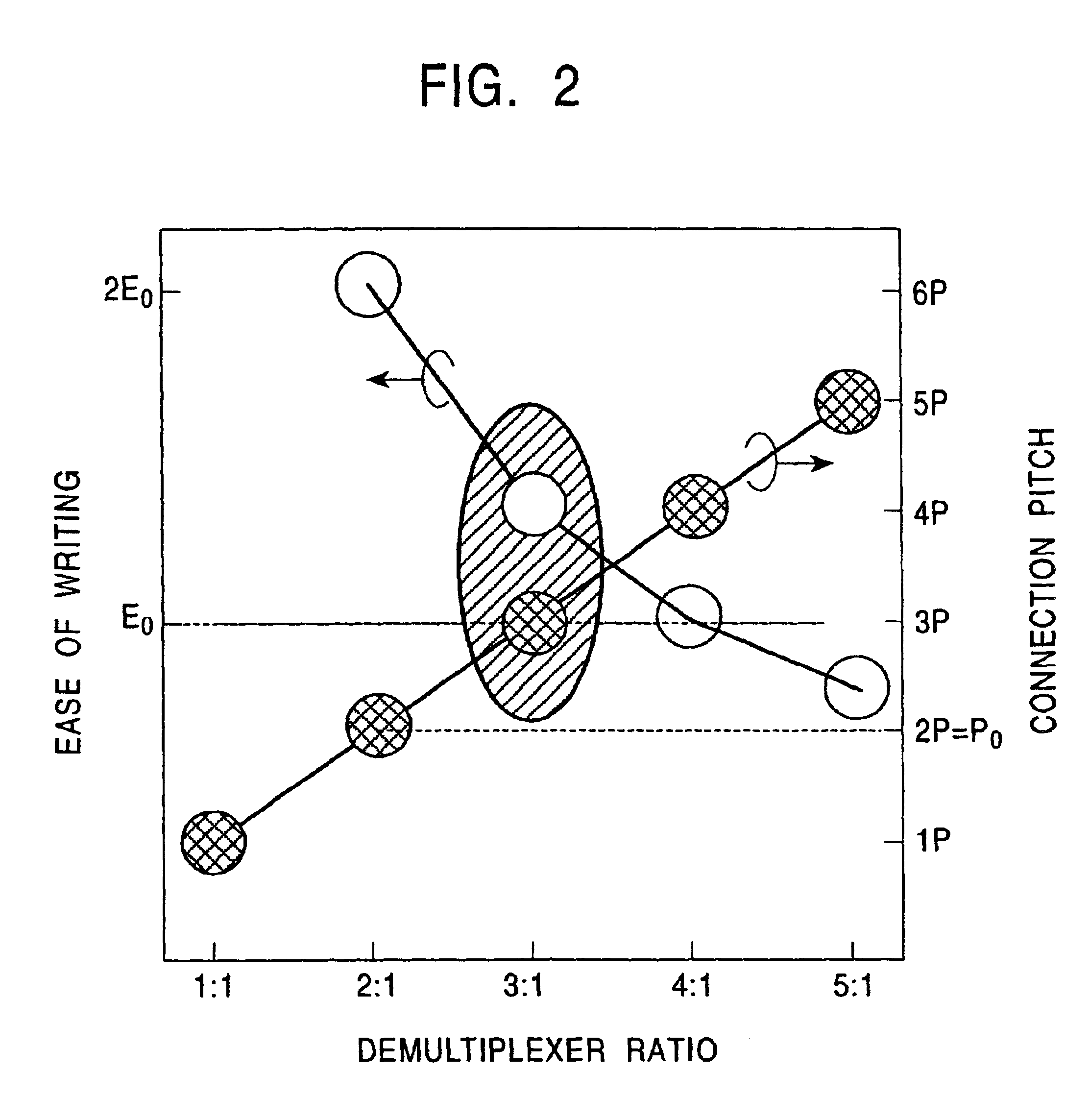
[0020]However, a switching unit temporally allocates a signal from an output of a source driver to a plurality of source lines, thus reducing the write time per pixel. As previously described, the ease of writing E1 at source drivers of a liquid crystal display which does not include a switching unit is improved by a factor of four over that of the conventional device. However, a liquid crystal display including a switching unit provides lower ease of writing than the ease of writing E1 as a signal is allocated to a larger number of source lines, and may provide even lower ease of writing than that of the conventional device if the number of source lines is increased by a large amount. Accordingly, the number of source lines allocated to a switching unit may be appropriately set to realize an LCD which satisfies requirements on both the ease of writing of signals and the ease of connection between source drivers and source lines.
[0023]Therefore, dot reverse driving source drivers are used to easily achieve dot reverse driving with less cross-talk.

Problems solved by technology

The higher the pixel density, the narrower the pixel pitch, leading to a narrower connection pitch between drivers and LCD signal lines, thus making it difficult to connect therebetween.
In particular, the pitch between source lines is inherently narrower than that between gate lines, and this problem is more noticeable.
Such a configuration, in which multiple source lines are allocated to two source drivers, is fast approaching the upper limit of fabrication and connection technology.
Furthermore, increasing the number of pixels throughout the display reduces the write time per pixel while simultaneously increasing the parasitic capacitance on a single source line, thus reducing the ease of writing the image signals.
Hence, the source drivers suffer from insufficient throughput and insufficient ability to drive electric current.
Therefore, another problem exists in that more sophisticated and more expensive source drivers are required.

Method used


Image

  • Active-matrix liquid crystal display suitable for high-definition display, and driving method thereof
  • Active-matrix liquid crystal display suitable for high-definition display, and driving method thereof
  • Active-matrix liquid crystal display suitable for high-definition display, and driving method thereof

Examples


Embodiment Construction

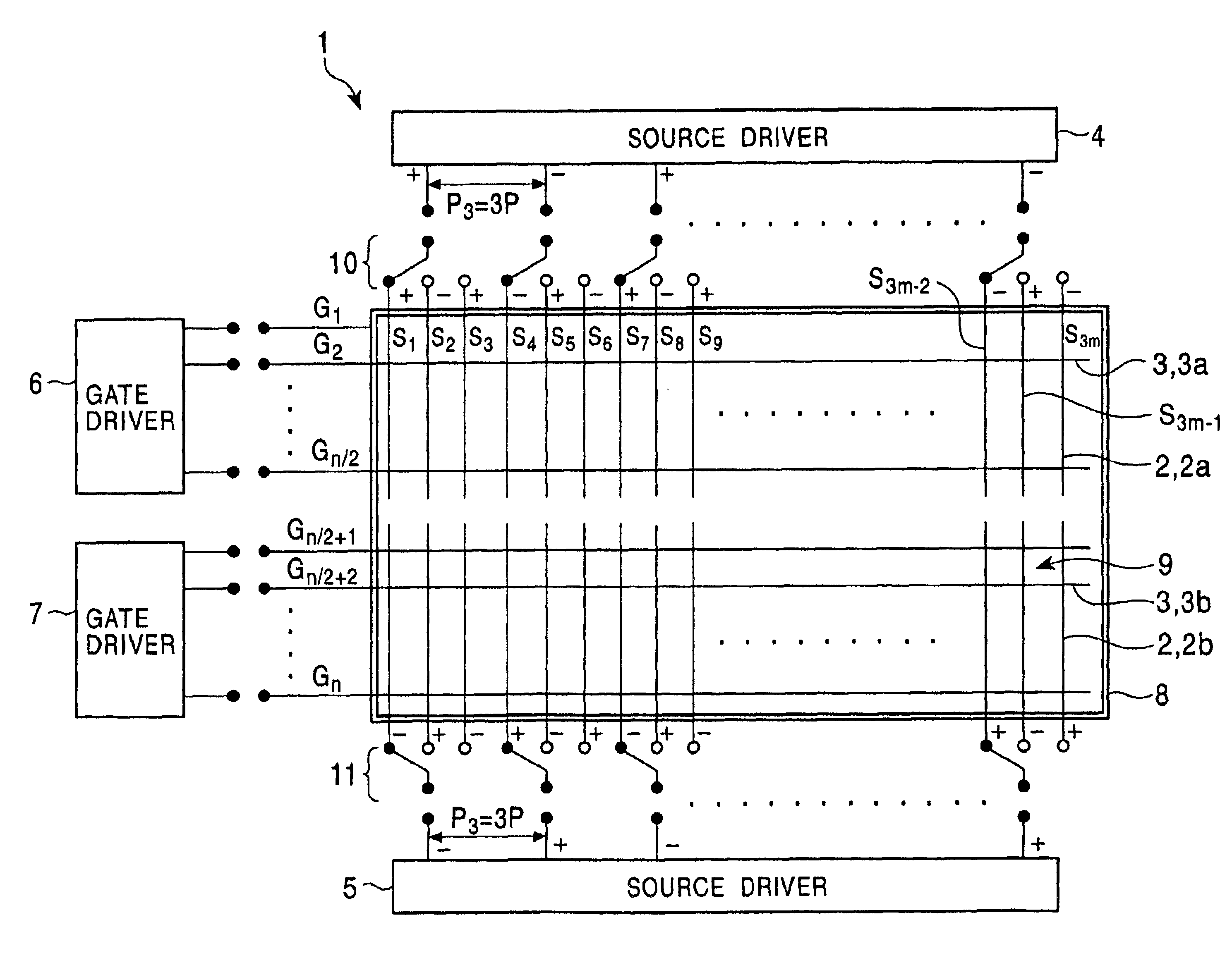
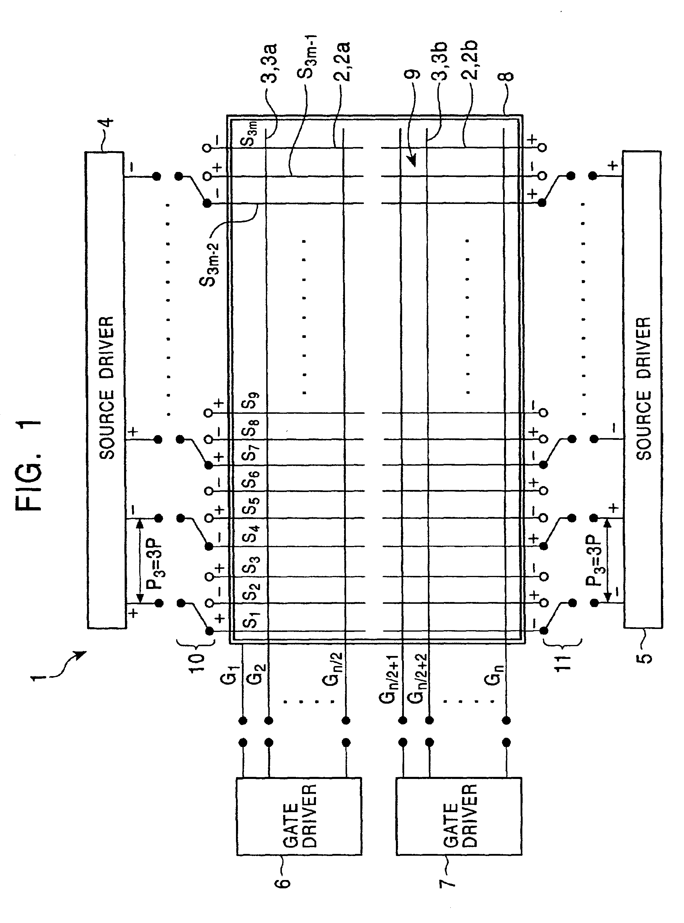
[0027]One embodiment of the present invention is described with reference to FIGS. 1 and 2.

[0028]FIG. 1 schematically shows a TFT active-matrix liquid crystal display 1 according to an embodiment of the present invention. The liquid crystal display 1 includes a first source driver 4, a second source driver 5, a first gate driver 6, and a second gate driver 7.

[0029]The liquid crystal display 1 has a plurality of source lines 2 (S1, S2, . . . , S3m−1, S3m) and a plurality of gate lines 3 (G1, . . . , Gn) arranged in a matrix on a display region 8. Regions defined by the source lines 2 and the gate lines 3 correspond to pixels. Each of the pixels includes a TFT and a pixel electrode although the components are not shown. The source lines 2 and gate lines 3 may be formed from any conducting material, preferably a metal such as Al if an opaque material is desired or InSnO if an optically transparent material is desired.

[0030]The plurality of source lines 2 are each divided into two group...


PUM


Abstract

A liquid crystal display having a plurality of source lines which are each divided into two groups includes a first source driver for applying image signals to a first group of the divided source lines, a second source driver for applying image signals to a second group, a first gate driver operative to apply scanning signals to one segment of a plurality of gate lines that extends across the first group of the divided source lines, and a second gate driver for applying scanning signals to the other segment of a plurality of gate lines that extends across the second group of the divided source lines. The liquid crystal display further includes 3:1 demultiplexers to switch and allocate an image signal from each of the first and second source drivers to three source lines.

Description

BACKGROUND OF THE INVENTION[0001]1. Field of the Invention[0002]The present invention generally relates to a liquid crystal display and a driving method thereof. More particularly, the present invention relates to the configuration of an active-matrix liquid crystal display suitable for high-definition display.[0003]2. Description of the Related Art[0004]In the art of liquid crystal displays (hereinafter sometimes abbreviated as LCDs) for use in a variety of electronic devices, the demand for improved image quality has increased, and high-definition displays have become more and more popular. In particular, in order to address the reduced pixel pitch and increased number of pixels in high-definition display, an LCD using a TFT active-matrix driving method in which a thin film transistor (hereinafter abbreviated as TFT) is used as a switching element in each pixel has been used. In one approach that has been proposed, a plurality of driver ICs allocate and apply image signals to mult...

Claims


Application Information

Patent Timeline
IPC IPC(8): G09G3/36G02F1/133G09G3/20
CPCG09G3/3666G09G2310/0297G02F1/133
Inventor HEBIGUCHI, HIROYUKI
Owner INTELLECTUAL VENTURES ASSETS 186 LLC
Learn More