Vascular surgical clamp for holding and guiding guide wire on a sterile field

Active Publication Date: 2015-09-08
ARRATIA ANSELMO
View PDF25 Cites 19 Cited by
  • Summary
  • Abstract
  • Description
  • Claims
  • Application Information

AI Technical Summary

Benefits of technology

The invention provides a lot of benefits, which are achieved through specific elements and combinations outlined in the claims. These benefits are not restricted to what is described in this patent and may include other benefits not directly explained in the text.

Problems solved by technology

However any retention device for the guide wires must not crimp or put a bend in the wire less the wire be rendered useless and have to be replaced which is not desired in a surgical procedure.
This process of going from a fixed position coil of wire being secured in a clamp and then into a guiding device for threading the wire or wires there through has created clutter on the sterile field and has required additional time for the surgical team to move from the release of the coiled wires to its insertion through a guiding device for further insertion into a patient.

Method used


Image

  • Vascular surgical clamp for holding and guiding guide wire on a sterile field
  • Vascular surgical clamp for holding and guiding guide wire on a sterile field
  • Vascular surgical clamp for holding and guiding guide wire on a sterile field

Examples


Embodiment Construction

[0031]Reference will now be made in detail to exemplary embodiments of the present invention which are illustrated in the drawings. Whenever possible, the same reference numbers will be used throughout the drawings to refer to the same or like parts.

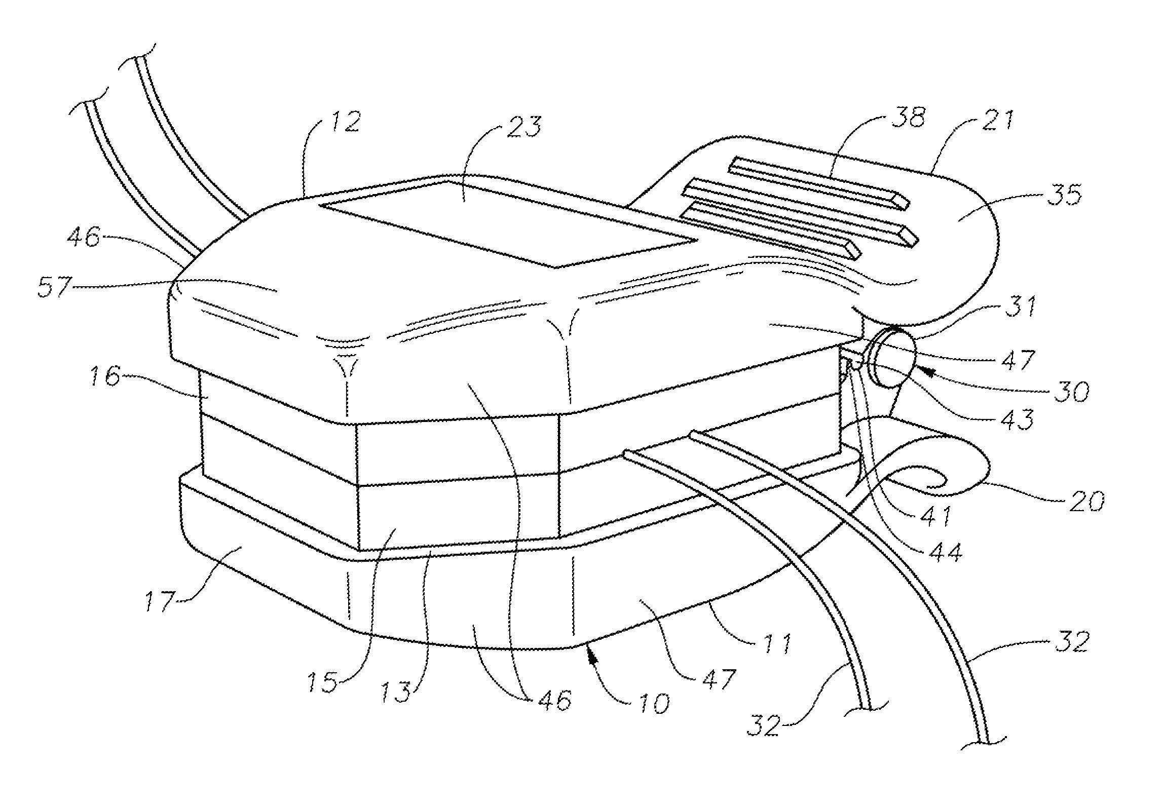
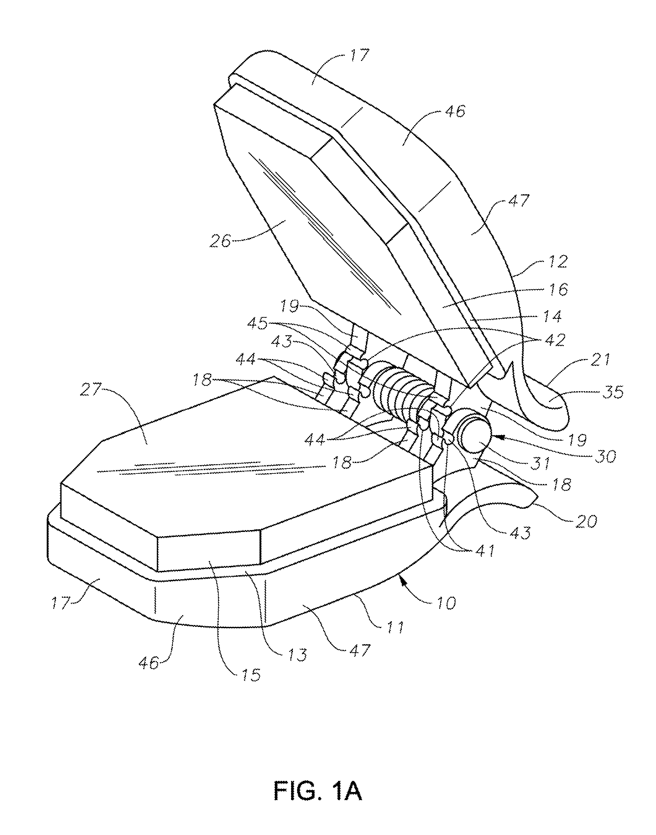
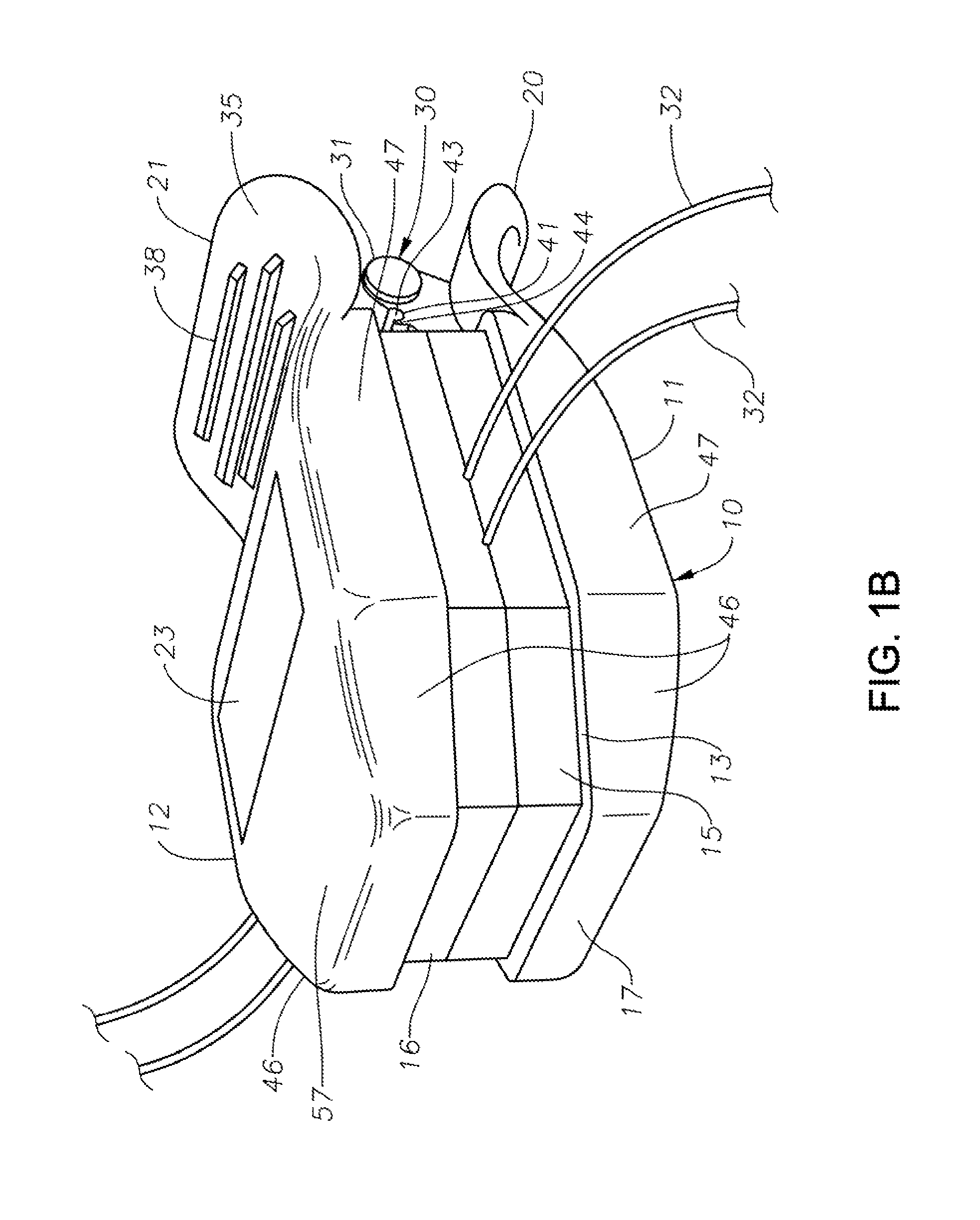
[0032]One example is shown in FIG. 1A and FIG. 1B of the surgical clamp 10 utilizing the principles of the present invention and while it is in a generally rectangular shape the clamp 10 can be any shape as long as it follows the principles of this present invention disclosed by the specification and claims. It will be appreciated that the surgical clamp 10 as shown in FIG. 1A and FIG. 1B are but examples of many forms of the surgical clamp 10 using the general principles of the present invention.

[0033]The surgical clamp 10 in FIG. 1A shows in general a first member 11 and second member 12 which are in facing relationship with each other and which have in general a receiving surface 13 on first member 11 and a receiving surface 14 on the...


PUM


Abstract

A cardiovascular surgical clamp used for retaining, identifying and positioning surgical wire for patients on a sterile field without wire injury. Opposing members with opposing recessed surfaces and back end portions are provided having removable compressible inserts with large flat matching surface areas inserted into the recesses of opposing members. The opposing members have spring / s located between them for driving them together and for manually opening them apart and have hinges formed on projecting struts for allowing simultaneous contact of the large flat matching surface areas of the removable compressible inserts for frictional engagement of wire without injury. The projecting struts of the opposing members provide guide wire surfaces proximate where hinges are formed for guiding wire there through. The opposing members and the projecting struts are moved from a closed to open position and back by compression or release of back end portions of the opposing members.

Description

BACKGROUND OF THE INVENTION[0001]1. Field of the Invention[0002]This present invention relates generally to a clamp device used in the field of cardiovascular procedures, which includes vessels of the coronary arteries and heart, for retaining, identifying and locating surgical wire, individual wires and or coils of wire without damage to the wire and wires for patients on a sterile field and providing guiding surfaces for moving a wire or wires there through in a surgical procedure without injury to the wire or wires being used in the patient.[0003]2. Background of the Invention[0004]In cardiovascular procedures, such as coronary artery procedures, the patient is laid out under a sterile drape and a sheath is inserted into the patient through a round opening in the sterile drape at a location such as the lower right or left groin area of the patient. During the procedure a guide wire is inserted through a sheath into the patient and has its proximal end moved to a location within t...

Claims


Application Information

Patent Timeline
IPC IPC(8): F16L3/22F16L3/10A61M25/09A61M25/02
CPCF16L3/1033A61M25/09A61M2025/09125A61M2025/024A61B2017/2808A61M25/013A61M2025/09116
Inventor ARRATIA, ANSELMO
Owner ARRATIA ANSELMO
Why Eureka
Try Eureka