Antenna Arrangement And A Method Relating Thereto

a technology of antenna and arrangement, applied in the direction of antenna details, space-fed arrays, antennas, etc., can solve the problems of time-consuming and expensive installation, long antennas, and long antennas, and achieve the effect of convenient fabrication or installation, convenient transportation, and convenient transportation

Inactive Publication Date: 2009-11-26
TELEFON AB LM ERICSSON (PUBL)
View PDF17 Cites 22 Cited by
  • Summary
  • Abstract
  • Description
  • Claims
  • Application Information

AI Technical Summary

Benefits of technology

The patent describes an antenna arrangement that can be easily mounted and has a high gain without requiring a large alteration of its beam width. It can be made aesthetically pleasing and resistant to high wind conditions. The arrangement has a flexible and adaptable design that allows for easy installation and control of its beam forming. It can be used with existing antenna parts and can be tilted in different directions for better coverage and reduced interference with neighboring cells. The arrangement also allows for easy mounting and disassembly, and it can be adapted to different conditions. Overall, the antenna arrangement provides an improved solution for high-gain, easy-to-mount, flexible, and adaptable antennas.

Problems solved by technology

However, even if mechanically long antennas are attractive for the reason mentioned above, there are several drawbacks associated with mechanically long antennas.
First, mechanically long antennas are cumbersome to handle, to transport and to mount.
Installation gets time-consuming and expensive.
As far as the provision of tilting is concerned, also in this respect there are several drawbacks associated with long antennas.
Pure mechanical tilt of a long antenna may result in the antenna deviating quite a lot from a vertical line, which means that it will typically not be parallel to the mast on which it is mounted.
Moreover, for mechanical tilting, a high wind load will result in a large torque which may cause damage to the antenna and may make it malfunction and it may even make it vulnerable to breaking entirely.
Moreover if the antenna is really long, a lot of mechanical tilting may be required; such antennas will be unaesthetic and the higher the antenna, the longer the required mechanical deviation and the more severe the drawbacks.
If on the other hand pure electrical tilt for a long antenna, with a given number of radiating elements, is implemented with only one or very few elements per sub-array, this requires a substantial amount of hardware.
However the scan range will also be reduced due to grating lobes resulting in gain reduction and reduced spatial filtering, which is disadvantageous.
Hence, so far no satisfactory solution has been suggested concerning the issue of providing an antenna which is as long as would be desirable for example from a coverage or gain point of view.

Method used


Image

  • Antenna Arrangement And A Method Relating Thereto
  • Antenna Arrangement And A Method Relating Thereto
  • Antenna Arrangement And A Method Relating Thereto

Examples


Embodiment Construction

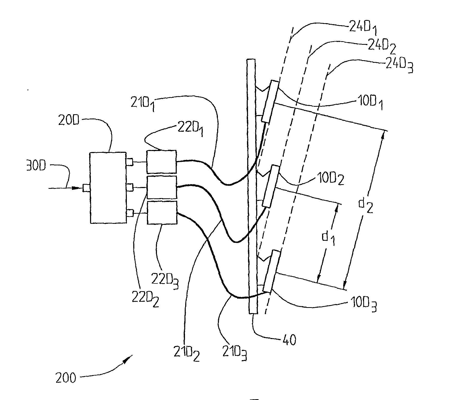
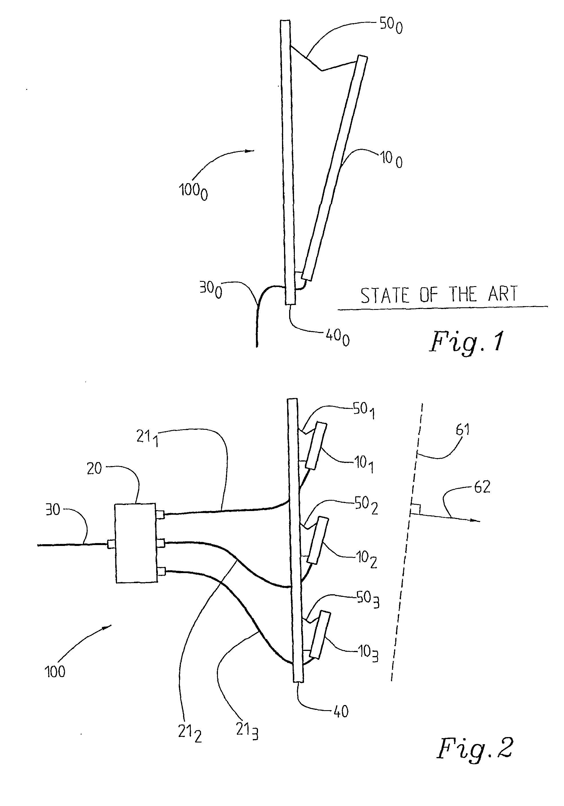
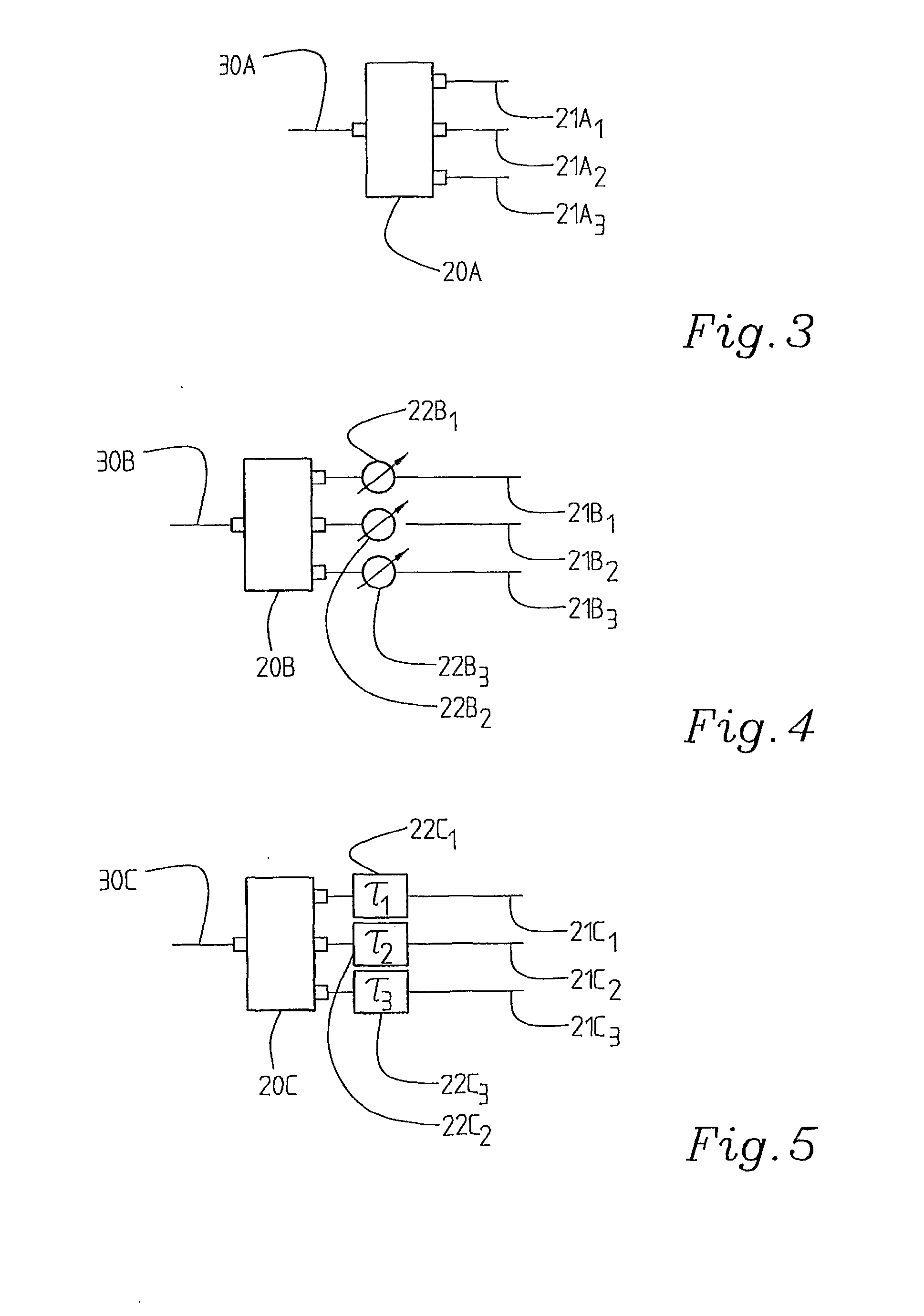
[0049]For the further understanding of the document, the terminology that is used will be briefly explained. An antenna element here designates an individual radiating element; mostly however, the term radiating element is used in the present document. A sub-array here means a group of antenna elements, i.e. radiating elements, which are arranged in such a way that they have a certain relation to each other. They are typically located on a straight line with equal or unequal spacing between respective antenna elements or radiating elements. An antenna section is a physical unit. It may for example be an off-the-shelf antenna or an antenna section fabricated specially for the purpose of providing a multi-section antenna. The antenna section may generate one or more beams, for example a dual polarized antenna. Particularly there is one RF-connector per beam. An antenna section may be a commercially available antenna, for example a sector antenna with 45°, 60° or 90° beam-width in azim...


PUM


Abstract

The present invention relates to an antenna arrangement (100) comprising an antenna section, said antenna section comprising a number of radiating elements which may be arranged in arrays or sub-arrays. It further comprises at least one further antenna section, said at least two antenna sections (101,102,103) being mounted substantially along a straight line, a non-straight line or irregularly at a mounting structure (40). It comprises a feeding network arrangement (20) for feeding said at least two antenna sections (101,102,103), with feeding network control means for controlling the feeding of the antenna sections (101r 102, 103) allowing for beam forming control.

Description

FIELD OF THE INVENTION[0001]The present invention relates to an antenna arrangement comprising an antenna section with a number of radiating elements which may be arranged in sub-arrays. The invention also relates to a method for controlling the beam forming in an antenna arrangement comprising an antenna section which in turn comprises a number of radiating elements which may be arranged in sub-arrays.STATE OF THE ART[0002]Antennas used today at the radio base stations of cellular mobile communication systems often are of the sector type. Three, six or more such antennas then cover, together, 360 degrees in azimuth. It is generally desirable to be able to extend the coverage of the radio base station. Then, however, high gain antennas are needed. Generally, the mechanically longer the antenna, the easier it is to provide a higher gain without altering the azimuth beam-width. However, even if mechanically long antennas are attractive for the reason mentioned above, there are several...

Claims


Application Information

Patent Timeline
Patent Type & Authority Applications(United States)
IPC IPC(8): H01Q3/00H01Q21/00
CPCH01Q21/0018H01Q1/246H01Q3/26H01Q3/32
Inventor DERNERYD, ANDERSPETERSSON, SVEN OSCARJOHANSSON, STEFANJOHANSSON, MARTIN NILS
Owner TELEFON AB LM ERICSSON (PUBL)
Why Eureka
Try Eureka