
Conveyor device for particulate material

a technology of conveying device and particulate material, which is applied in the direction of conveyors, conveyors, transportation and packaging, etc., can solve the problems of expensive and time-consuming development of dryer-specific conveying lines and suction lines, and achieve the reduction of design and installation costs of conveying lines and suction lines, and the complexity of conveying lines and vacuum lines

Inactive Publication Date: 2005-08-02
MANN & HUMMEL PROTEC GMBH
View PDF13 Cites 27 Cited by
  • Summary
  • Abstract
  • Description
  • Claims
  • Application Information

AI Technical Summary

Benefits of technology

[0006]Another object of the invention is to provide a conveying device for particulate material in which the complexity of conveying lines and vacuum lines is decreased.
[0007]A further object of the invention is to provide a conveying device for particulate material in which the design and installation costs of conveying lines and suction lines is reduced.
[0009]For this purpose, the handling devices in the conveyor apparatus according to the invention are connected to a conveying line common to all the handling devices, and an air pressure sensor provided on the suction line controls a control member that is disposed on the suction probe to control the air flow rate through the conveying line. This eliminates the need for conveying lines and suction lines designed specifically for each handling device. It nevertheless assures that a substantially constant suction pressure for transporting granulate into a handling device is always present in the conveying line. This is true irrespective of the length of the effective conveying line between the suction probe and the respective handling device.
[0011]Preferably, each handling device on the conveying line has its own connecting nipple and a connecting line leading from the connecting nipple to the handling device. This makes it possible to install the conveying line largely in a straight line.

Problems solved by technology

The development of dryer-specific conveying lines and suction lines, however, is costly and time consuming.

Method used


Image

  • Conveyor device for particulate material
  • Conveyor device for particulate material

Examples


Embodiment Construction

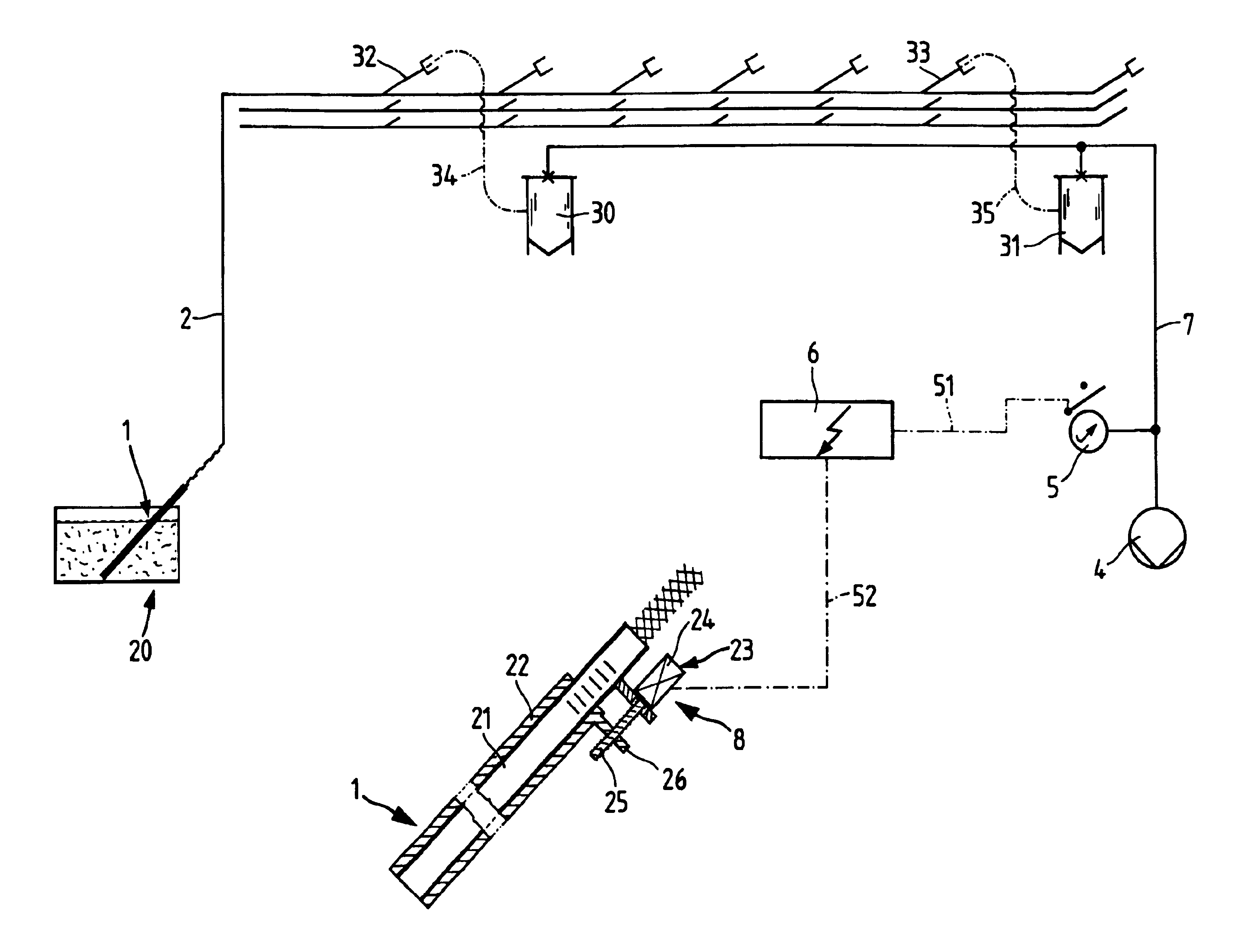
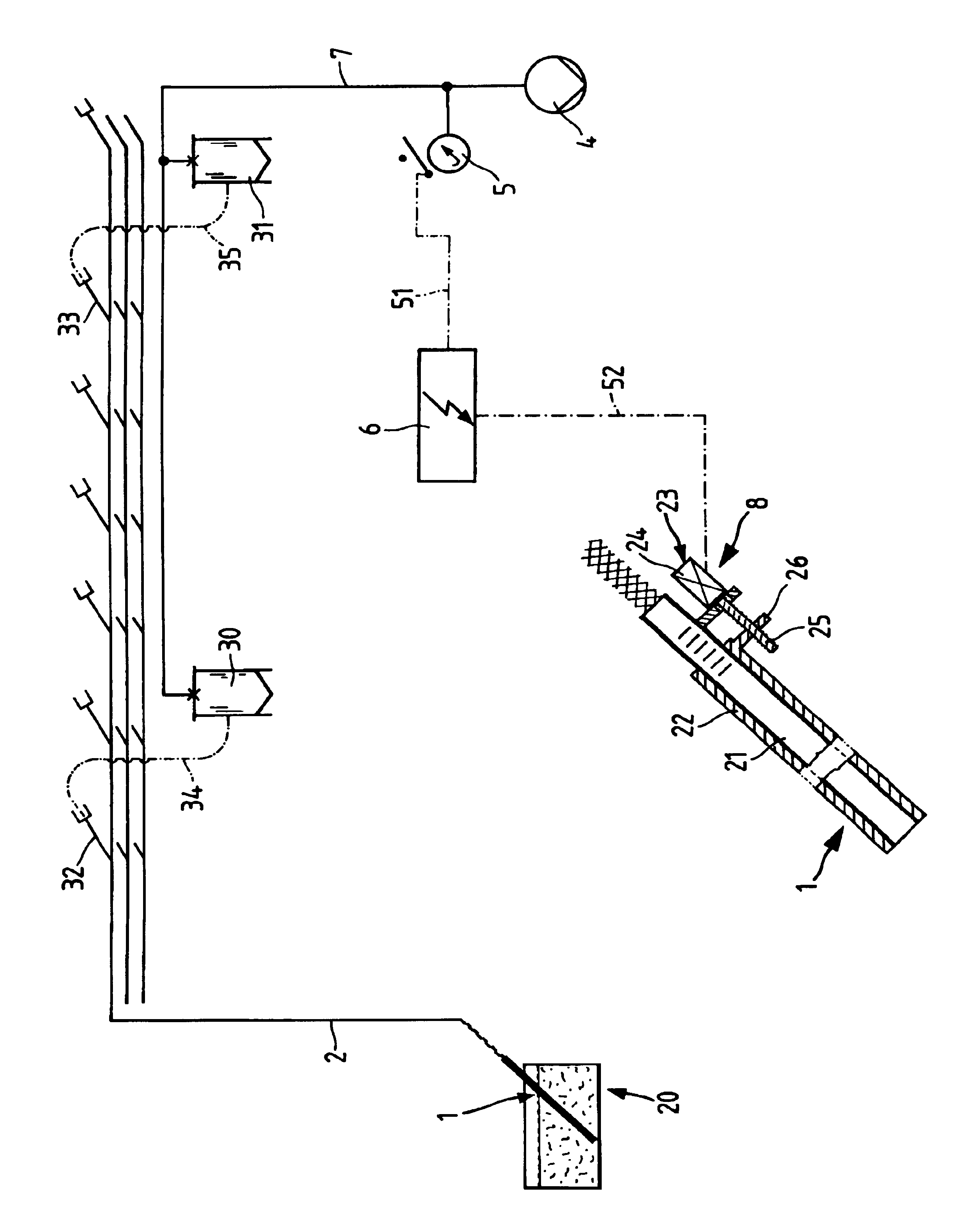
[0015]One end of a material-specific conveying line 2 terminates in a suction probe, which as a whole is identified by the numeral 1 and which in the operation of the illustrated conveyor apparatus is extended into a moisture-laden synthetic resin granulate. The synthetic resin granulate is located in a storage bin or vessel 20, which is replenished with synthetic resin granulate to maintain a sufficient level.

[0016]A plurality of spaced apart connecting nipples, the number of which is not subject to any limitation, is attached along the length of the conveying line 2. The figure shows two of these, identified as connecting nipples 32 and 33. A connecting line 34 leads from the connecting nipple 32 to the inlet of a handling device 30, which can be a dryer such as the one described in the cited prior art. A connecting line 35 leading to the inlet of a handling device 31 is connected to the connecting nipple 33, which is spaced at a substantial distance from connecting nipple 32 alon...


PUM


Abstract

A conveyor apparatus for a particulate material to be conveyed, e.g., a synthetic resin granulate or powder, with a plurality of handling devices (30, 31) for processing the conveyed material, a storage bin (20) for the material to be conveyed, a conveying line (2) provided with a suction probe (1) for withdrawing the material to be conveyed from the storage bin, and a negative pressure source (4) connected to the handling devices via a suction line (7). The handling devices (30, 31) are all connected to a common conveying line (2), and a control member (8) is provided on the suction probe (1) to control the air volume going through the conveying line (2). This control member is controlled by an air pressure sensor (5) disposed on the suction line (7).

Description

BACKGROUND OF THE INVENTION[0001]The present invention relates to a conveyor apparatus for a pourable material to be conveyed, for example a synthetic resin (i.e., plastic) granulate or powder, with a plurality of handling devices for processing the material to be conveyed, a storage bin for the material to be conveyed as well as a conveying line provided with a suction probe or wand for sucking in the material to be conveyed and a low pressure source connected to the conveying devices via a suction line.[0002]To produce synthetic resin articles that are made, for example, of thermoplastic polyester, such as polyethylene terephthalate (PETP), using an injection molding machine, a dry synthetic resin granulate is fed to this machine. Because the synthetic resin granulate often contains moisture when delivered, this moisture must be removed from the granulate before it is supplied to the processing machine. To remove the moisture, substantially cylindrical dryers are used into which t...

Claims


Application Information

Patent Timeline
IPC IPC(8): B65G53/04B65G53/42B65G53/66B65G53/24B65G53/34B65G53/40
CPCB65G53/24B65G53/42B65G53/66B65G2201/042
Inventor GOTH, GERHARD
Owner MANN & HUMMEL PROTEC GMBH
Learn More