Gas sensor and method of heating the same

a technology of gas sensor and heating unit, which is applied in the direction of liquid/fluent solid measurement, electrochemical variables of materials, instruments, etc., can solve the problems of large amount of nox produced and the inability to measure the concentration of nox, and achieve the effect of increasing the resistance of the heating uni

Inactive Publication Date: 2005-07-26
NGK INSULATORS LTD
View PDF13 Cites 16 Cited by
  • Summary
  • Abstract
  • Description
  • Claims
  • Application Information

AI Technical Summary

Benefits of technology

[0012]increasing the temperature of the heater rapidly when the temperature of the substrate is low; and
[0014]In this method, when the control mode of the heater is switched to feedback control, temperature of the substrate is not increased excessively rapidly. Therefore, it is possible to prevent formation of cracks in the substrate.
[0017]Preferably, the heater has a heating unit, and a resistance of the heating unit of the heater is measured and controlled for increasing the temperature of the heater so that the temperature of the heater can be controlled easily.
[0020]means for controlling a rate of increasing the resistance of the heating unit per unit time.

Problems solved by technology

In general, when the amount of fuel is not enough in combustion, a large amount of NOx is produced.
Therefore, it is not possible to measure the concentration of NOx.

Method used


Image

  • Gas sensor and method of heating the same
  • Gas sensor and method of heating the same
  • Gas sensor and method of heating the same

Examples


embodiment 1

[0144]The gas sensor of the embodiment 1 uses the control switching circuit 330B of the second example. The temperature of the heater 64 is increased at a speed not more than 40 degrees centigrade / sec. when the temperature of the substrate is 600 degrees centigrade or more. The temperature of the heater 64 is increased at a speed not more than 100 degrees centigrade / sec. when the temperature of the substrate is 500 degrees centigrade or less.

[0145]The range of gas flow rate for the first experiment is determined based on an automobile application. The experiment is performed at a room temperature while changing the gas flow speed by a gas blower. In FIG. 15, results of the comparative example 1 are plotted by squares, and results of the embodiment 1 are plotted by circles. It can be seen that the defective rate of the comparative example 1 is shown by a curve A, and the defective rate of the embodiment 1 is shown by a curve B.

[0146]According to the experiment, no formation of cracks...

embodiment 2

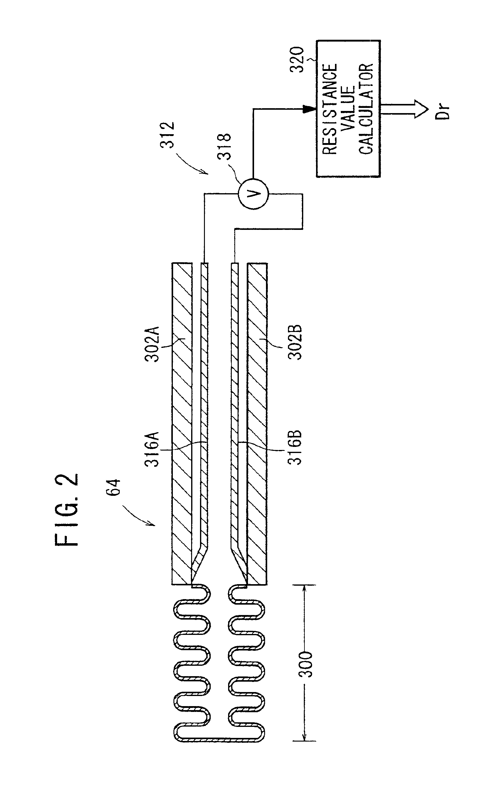
[0151]In contrast, in the embodiment 2, the gas sensor has the voltage measuring lead (316A, for example). The resistance of the heating unit 300 is directly controlled at a constant value. Therefore, when the substrate is heated and the temperature of the current lead 302A, 302B is increased, the change in the temperature of the substrate 200 is small. Thus, the controllability of the heater 64 is not affected substantially by the change of the gas temperature.


PUM

PropertyMeasurementUnit
temperatureaaaaaaaaaa
electric currentaaaaaaaaaa

Abstract

Temperature of a heater is controlled by switching an increasing rate of a resistance value of heating unit of the heater. During a period T1 from a time point when heating of the heater is started until the resistance value of the heating unit reaches a reference value, the increasing rate is changed in multiple heating stages. In this manner, the temperature and the resistance value of the heating unit are increased. During a period T2 from a time point when the resistance value of the heating unit reaches the reference value, feedback control is performed such that the resistance value is kept at the reference value as a target value.

Description

BACKGROUND OF THE INVENTION[0001]1. Field of the Invention[0002]The present invention relates to a gas sensor having a ceramic substrate in which a heater for heating the gas sensor is embedded. Further, the present invention relates to a method of heating the gas sensor. The gas sensor measures oxides such as NO, NO2, SO2, CO2, and H2O and inflammable gases such as CO and CnHm in atmospheric air and exhaust gas discharged from vehicles.[0003]2. Description of the Related Art[0004]Various measuring systems and apparatuses for measuring concentration of gas components in a measurement gas have heretofore been proposed.[0005]For example, according to a method of measuring concentration of NOx in a measurement gas such as exhaust gas, Nox-reducing ability of Rh is utilized. A sensor having a Pt electrode and an Rh electrode formed on an oxygen ion-conductive solid electrolyte such as zirconia is used to measure an electromotive force generated between the electrodes.[0006]However, the ...

Claims


Application Information

Patent Timeline
Patent Type & Authority Patents(United States)
IPC IPC(8): G01N27/406H05B1/02H05B3/14G01N33/00G01N27/419G01N27/409G01N27/416
CPCG01N27/4067H05B1/0236H05B3/141G01N33/0037Y02A50/20
Inventor KATO, NOBUHIDEKATO, KIMIEMIYASHITA, TAKEYA
Owner NGK INSULATORS LTD
Why Eureka
Try Eureka