
Solder protective coating and fluxless joining of flip chip devices on laminates with plated solder

a technology of flip chip and protective coating, which is applied in the field of fluxless joining of flip chip devices on laminates with plated solder, can solve the problems of sn(iv) being difficult to complex, affecting the solder process, and easy to leave a clean surface easily wet, so as to facilitate the reflow of solder and facilitate the wetting of solder

Inactive Publication Date: 2005-07-26
IBM CORP
View PDF13 Cites 1 Cited by
  • Summary
  • Abstract
  • Description
  • Claims
  • Application Information

AI Technical Summary

Benefits of technology

[0008]The invention provides a method of protecting tin solderable surfaces. To a solderable surface, coated with tin oxide, a complexing agent is applied. The complexing agent is, a dicarboxylic acid, for example, pimelic acid. Heating drives the formation of tin pimelate which forms a tenacious film over the solder surface protecting it from reacting further with ambient oxygen. The protective agent, tin pimelate in this example, also prevents the oxidation of Sn(II) to Sn(IV). Sn(IV) is well known to be difficult to complex and to inhibit the solder process.
[0009]The invention provides a means of generating clean metal surfaces for solder joining without incurring problems associated with the use of customary flux. An aspect of the invention is that the temperatures associated with reflow decompose the protective agent to volatile materials, in the present example, tin pimelate is decomposed to cyclohexanone and CO2. The decomposition results in a clean surface.
[0010]An additional aspect of the invention is provision of means of protection against oxidation of solderable surfaces during storage awaiting final assembly.
[0011]Yet a further aspect of the invention is provision of means by which flux contamination of extraneous surfaces is prevented. The present invention eliminates the need for flux, usually required for multiple reflow steps, and minimize the further growth of the tin oxide layer. The present invention substantially eliminates flux residues since the decomposition products are gaseous.

Problems solved by technology

The tin carboxylate complex facilitates solder reflow, but moreover, when exposed to peak reflow temperatures, decomposes into volatile products, leaving a clean surface easily wetted by the solder.
Sn(IV) is well known to be difficult to complex and to inhibit the solder process.

Method used


Image

  • Solder protective coating and fluxless joining of flip chip devices on laminates with plated solder
  • Solder protective coating and fluxless joining of flip chip devices on laminates with plated solder

Examples


Embodiment Construction

[0015]Reference is made to the figures to illustrate selected embodiments and preferred modes of carrying out the invention. It is to be understood that the invention is not hereby limited to those aspects depicted in the figure.

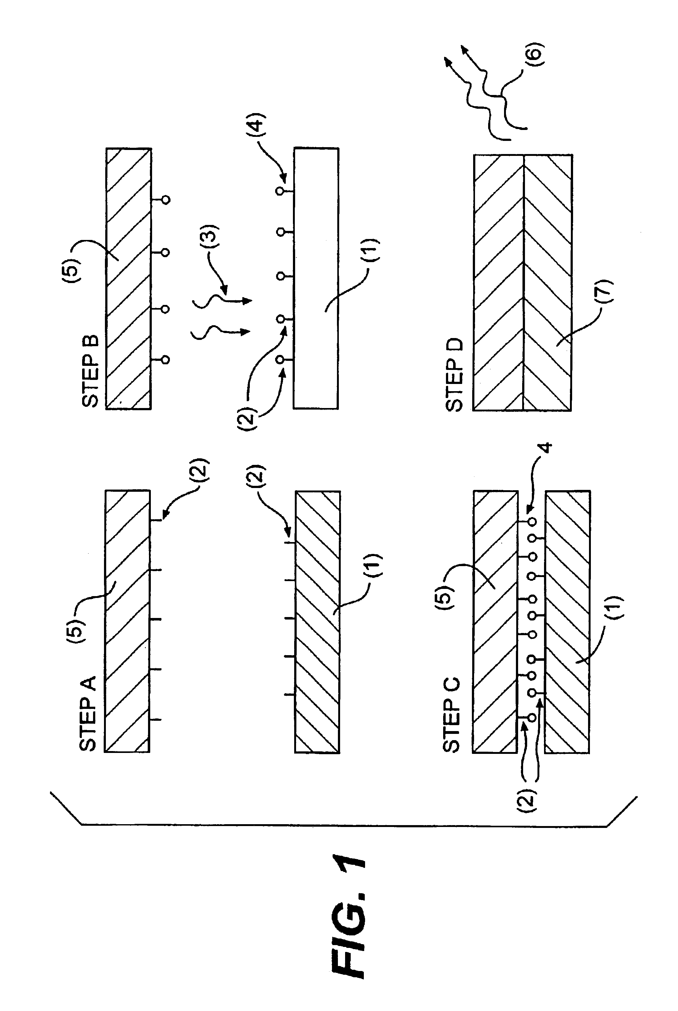
[0016]In Step A, a first tin solderable surface 1 and a second tin solderable surface 5, each of the surfaces having a natural film of tin oxide 2 thereon, are provided. In Step B, a complexing agent 3 is applied. In some embodiments of the invention, the complexing agent is pimelic acid applied from a vapor phase. The complexing agent forms an addition product 4 with the oxide coating, in some embodiments, a cyclic tin pimelate product. In some embodiments of the invention, the parts, with solder joinable surfaces protected by the addition product, are stored for later final assembly. Step C intimately contacts the first and second surfaces. In Step D, reflow conditions are applied, forming a solder joint, decomposing the addition product to volatile materi...


PUM

PropertyMeasurementUnit
Temperatureaaaaaaaaaa

Abstract

A method for protecting tin oxide coated solder surfaces against further oxidation and a method for fluxless solder joining of such surfaces is provided.

Description

CROSS REFERENCE TO APPLICATION[0001]This application is a divisional application of Ser. No. 09 / 687,524, filed Oct. 12, 2000 now U.S. Pat. No. 6,585,150.FIELD OF THE INVENTION[0002]The invention relates to the fluxless joining of flip chip devices on laminates with plated solder. The invention also relates to the protection of such solder joinable surfaces against excess oxidation.BACKGROUND OF THE INVENTION[0003]Fluxes are commonly reacted with surface oxides, such as tin oxide, during the reflow process to generate metal surfaces which subsequently intermix forming a solder joint. Problems in fluxing and soldering can arise in which inadequate amounts of flux or excessive thicknesses of tin oxide are present either or both of which can inhibit wetting and intermixing and result in the formation of non wetted, electrically open solder joints. In addition, where excess flux may be incompletely consumed in the reflow process. The remaining residues will interfere with the efficiency ...

Claims


Application Information

Patent Timeline
IPC IPC(8): C23C26/00C23C8/00H05K3/28B23K35/22H05K3/34H01L21/60
CPCC23C8/00C23C26/00H01L24/81H05K3/282B23K35/226H01L2224/81801H05K3/3457H01L2924/01005H01L2924/01006H01L2924/01033H01L2924/0105H01L2924/014
Inventor BERNIER, WILLIAM E.HENDERSON, DONALD W.SPALIK, JAMESPAQUIN, ISABELLE
Owner IBM CORP
Learn More