
DC power supply using fuel cell

a fuel cell and power supply technology, applied in the direction of dc source parallel operation, electric generator control, machines/engines, etc., can solve the problems of voltage conversion and electric power loss, and achieve the effect of improving the output efficiency of a direct current (dc) power supply

Inactive Publication Date: 2005-07-26
TOYOTA JIDOSHA KK
View PDF17 Cites 45 Cited by
  • Summary
  • Abstract
  • Description
  • Claims
  • Application Information

AI Technical Summary

Benefits of technology

[0006]It is an object of the invention to provide a technology that improves an output efficiency of a direct current (DC) power supply using a fuel cell and a chargeable / dischargeable electric power storage unit in combination.
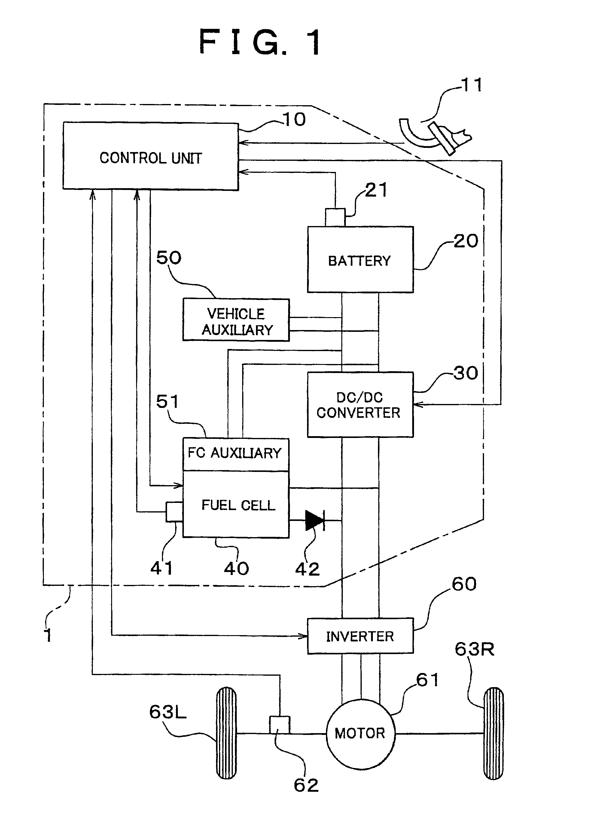
[0008]In a typical DC-DC converter, a loss of the electric power is caused by voltage conversion. The invention may prevent the loss of the electric power generated by the fuel cell by connecting the DC-DC converter to the electric power storage unit. In a typical power supply system having a fuel cell and an electric power storage unit, the electric power is mainly supplied from the fuel cell. Accordingly, the output efficiency of the entire power supply system can be improved by preventing the loss of the electric power supplied from the fuel cell. Since the fuel cell is used more frequently than the battery, the invention is effective especially when a maximum output power of the fuel cell is greater than a maximum output power of the electric power storage unit.
[0010]The FC accessories include various devices required for the system configuration of the fuel cell, such as a pump that supplies a fuel gas, a heater required for extracting hydrogen from a hydrogen absorbing alloy, or a reformer that reforms a material such as methanol to produce the fuel gas. According to the aforementioned configuration, the FC accessories are supplied with the electric power directly from the electric power storage unit. The electric power can be directly supplied to the FC. Therefore the FC accessories, and accordingly, the fuel cell can be operated irrespective of failure in the DC-DC converter. In the above structure, even in the state where the fuel cell is not sufficiently warmed up to generate the electric power, operation of the FC accessories independent of the DC-DC converter makes it possible to warm up and start the fuel cell. The invention is not limited to a configuration in which all the FC accessories are connected to the electric power storage unit. For example, at least a part of the FC accessories required for warming up the fuel cell may be connected to the electric power storage unit, and the rest of the FC accessories may be connected to the fuel cell.
[0011]In the invention, an output voltage of the DC / DC converter is controlled to be substantially equal to an output voltage of the fuel cell. The aforementioned control makes it possible to generate the electric power by operating the electric power storage unit to compensate for the response delay in the output of the fuel cell with respect to the required electric power.

Problems solved by technology

In a typical DC-DC converter, a loss of the electric power is caused by voltage conversion.

Method used


Image

  • DC power supply using fuel cell
  • DC power supply using fuel cell
  • DC power supply using fuel cell

Examples


Embodiment Construction

[0022]An embodiment of the invention to be used in a hybrid vehicle will be described in the following sections.

A. System configuration:

B. Electric power control routine:

C. Output ratio setting:

D. Effect:

A. System Configuration

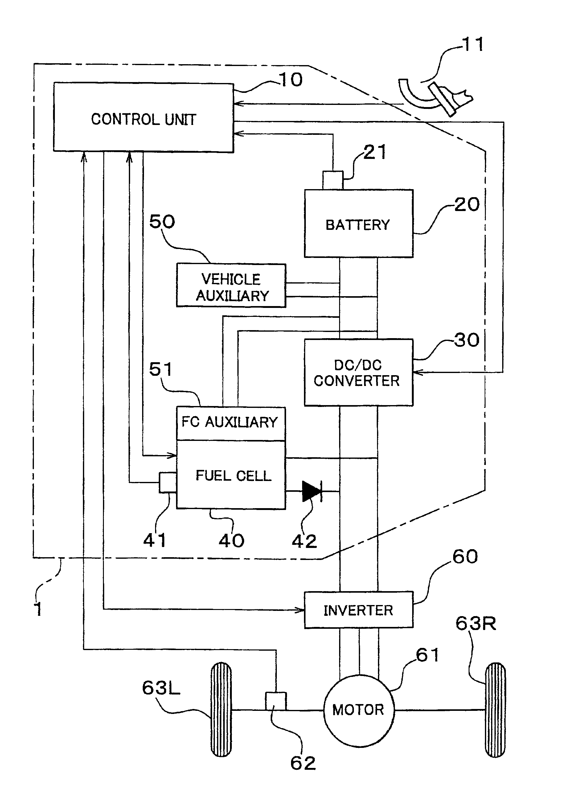
[0023]FIG. 1 is a schematic diagram illustrating a vehicle that employs a power supply system as an embodiment of the invention. The vehicle is driven by a synchronous motor 61 as a driving power source coupled to wheels 63L and 63R. The synchronous motor 61 is driven by a power supply system 1. Direct current output from the power supply system 1 is inverted by an inverter 60 into a three-phase alternating current to be supplied to the synchronous motor 61. The synchronous motor 61 may be constructed to serve as a generator when the vehicle is in a braking state.

[0024]The power supply system 1 includes a fuel cell 40, a battery 20 as the electric power storage unit, and a DC-DC converter 30 and the like. The fuel cell 40 generates electric power through elect...


PUM

PropertyMeasurementUnit
electric currentaaaaaaaaaa
weightaaaaaaaaaa
electric poweraaaaaaaaaa

Abstract

A power supply system includes a fuel cell and a battery connected in parallel. A DC-DC converter is connected to the battery. A maximum output ratio of the fuel cell and the battery is set to be in a range where the output of the fuel cell is within 65 to 80% of the total output. Accordingly, electric power loss owing to conversion performed by the DC-DC converter is reduced to achieve a high energy efficiency.

Description

INCORPORATION BY REFERENCE[0001]The disclosure of Japanese Patent Application No. 2000-304595 filed on Oct. 4, 2000 including the specification, drawings and abstract is incorporated herein by reference in its entirety.BACKGROUND OF THE INVENTION[0002]1. Field of the Invention[0003]The invention relates to a DC power supply using a fuel cell.[0004]2. Description of Related Art[0005]Fuel cells have been gaining much attention in recent years as a power supply with a high operation efficiency and environmental characteristics. A fuel cell generates electricity through an electrochemical reaction of hydrogen and oxygen and outputs electric power as required by controlling an amount of a fuel gas to be supplied. In some cases, however, the response of the electric power output is lowered due to the delay in supply of the fuel gas. In order to avoid the aforementioned problem, a technique in which a fuel cell and a battery are connected in parallel to constitute a power supply system has...

Claims


Application Information

Patent Timeline
Patent Type & Authority Patents(United States)
IPC IPC(8): B60L11/18H01M8/04H01M16/00B60L1/00H02J7/34H01M8/00H02J1/00H02J1/10
CPCB60L11/1881B60L11/1894H01M8/04388H01M8/04395H01M8/04626H01M8/04753H01M8/0488H01M8/04992H01M16/006B60L2210/10H01M2250/20Y02T10/7216Y02T90/32Y02T90/34Y02E60/50B60L58/30B60L58/34Y02T10/72Y02T90/40Y02E60/10
Inventor SUGIURA, HIROSHIISHIKAWA, TETSUHIROWATANABE, NOBUOMANABE, KOUTA
Owner TOYOTA JIDOSHA KK
Learn More