
Membrane module for the hemodiafiltration with integrated pre- or postdilution of the blood

a hemodiafiltration and membrane module technology, applied in the field of membrane module for hemodiafiltration, can solve the problems of complex operation of the hemodiafiltration apparatus with blood filters connected in series, can not be used in commercially available dialysis machines, special regenerators, purifying ultrafiltrate, etc., and achieves the effect of improving the ability to predetermine and reproduce the delivery and simple and compact construction

Inactive Publication Date: 2005-07-19
MEMBRANA
View PDF18 Cites 86 Cited by
  • Summary
  • Abstract
  • Description
  • Claims
  • Application Information

AI Technical Summary

Benefits of technology

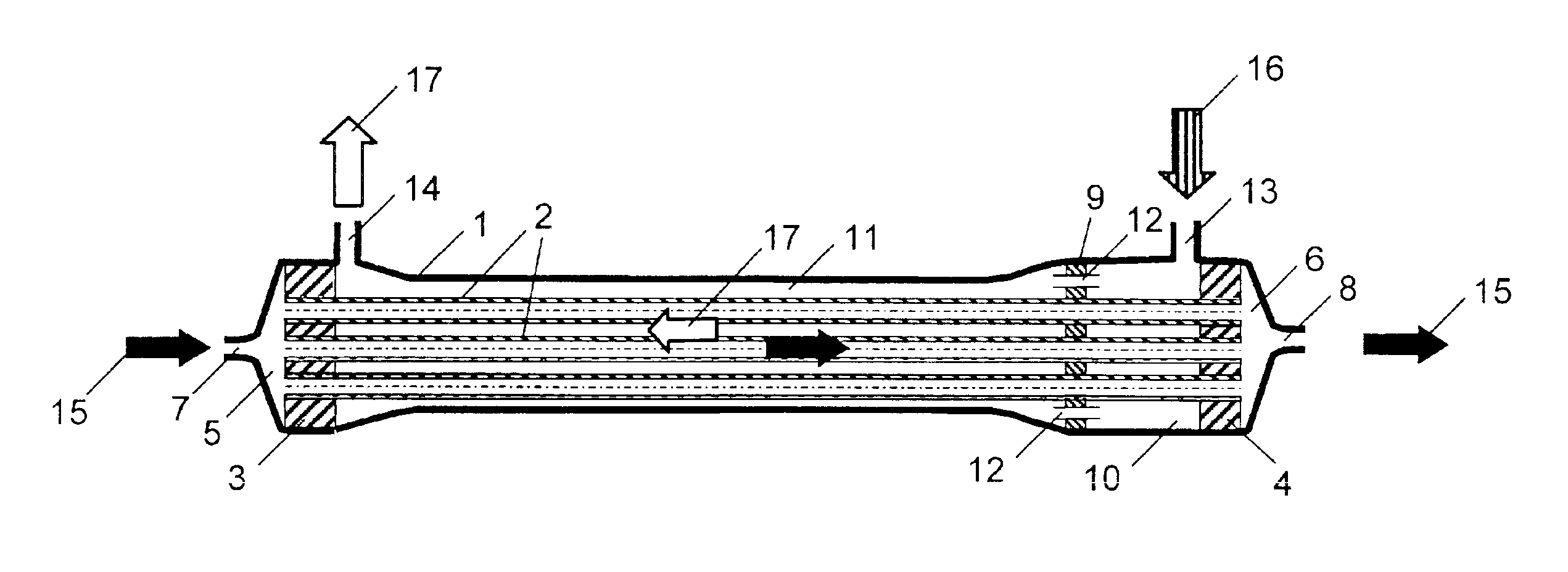
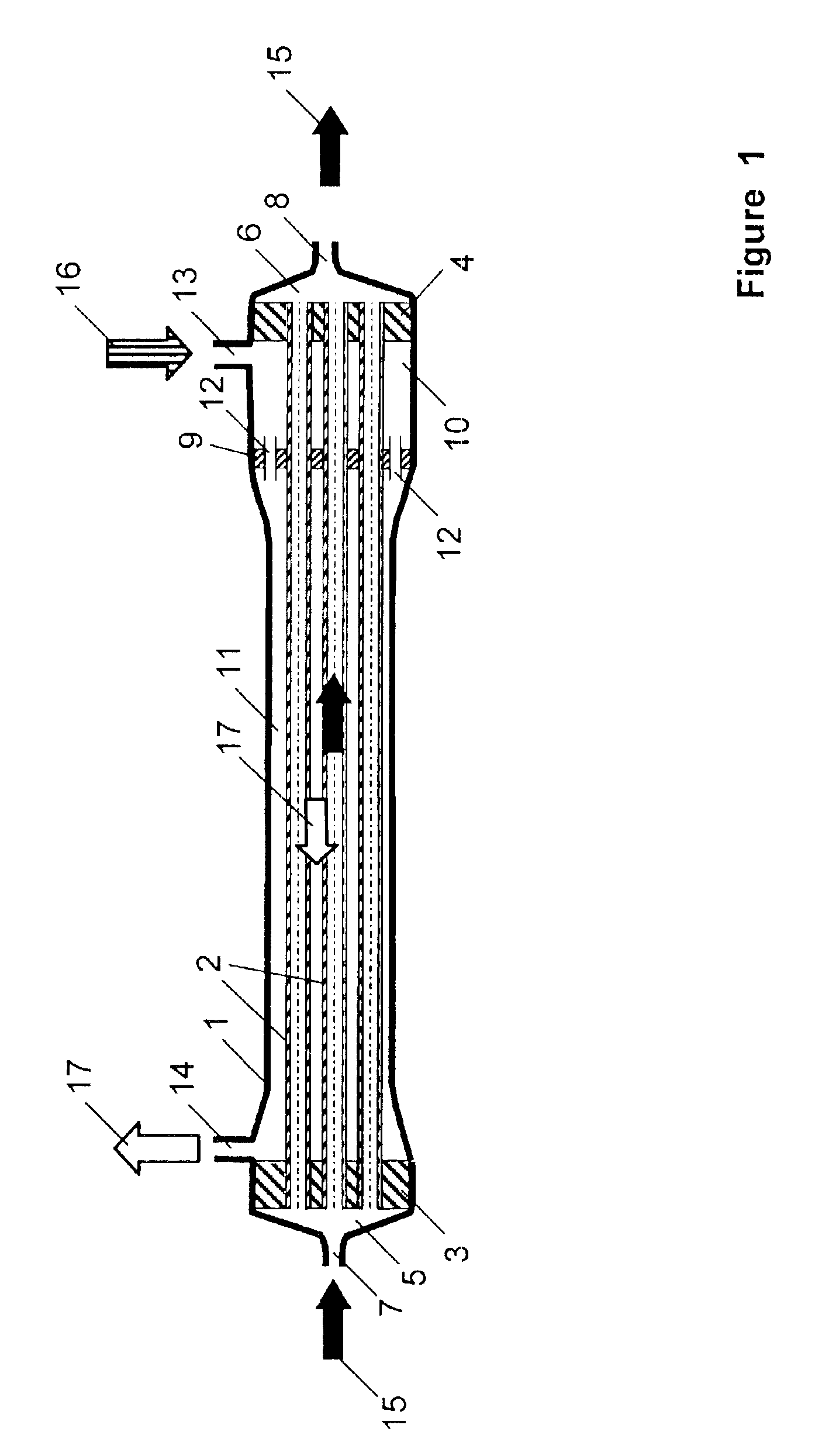
[0021]It is therefore an object of the present invention to provide a membrane module for hemodiafiltration that has a simple and compact construction, exhibits an improved ability to predetermine and reproduce the delivery of substituate and dialyzate, and can be used in volume-controlled dialysis machines without major modifications.

Problems solved by technology

However, with an endotoxin concentration of <0.03 EU / ml, which is the detection limit of the conventional LAL tests, CIS might still be present in the dialyzate.
Such hemodiafiltration apparatus with blood filters connected in series are complex in operation and can generally not be used in commercially available dialysis machines due to the design and the special and complex controls associated with it.
In addition to the previously cited disadvantages of separate blood filters connected in series, the hemodiafiltration apparatus described in EP-A 451 429 has the drawback that it requires a special regenerator that must be used to purify the ultrafiltrate.
While the hemodiafiltration system described in DE-A 196 07 162 has a simpler and clearer construction compared to the systems with multiple blood filters connected in series, the manufacture of the two-module dialyzers disclosed in DE-A 196 07 162 is difficult, particularly due in part to the handling of two different hollow-fiber membrane bundles.
Furthermore, the membrane modules in the dialyzer are not arranged rotationally symmetrically, so that there is a risk of non-uniform flow, in particular through the external space surrounding the hollow-fiber membranes of the first membrane module, which is used for hemodiafiltration.
In this hemodiafilter, a material is present in the external space of the hemodiafilter surrounding the hollow-fiber membranes that undergoes dimensional changes, i.e., swells, through the dialysis liquid when this hemodiafilter is used for hemodiafiltration, leading to a restriction.
The insertion of the swellable material is complex, on one hand.
On the other hand, a precise, stable, and reproducible positioning across the bundle cross-section is not guaranteed and cannot be achieved in practice.
There are also narrow limits imposed on the materials capable of swelling that can be used since the use of the hemodiafilter for blood purification requires a high degree of hemocompatibility for the materials used, due to the contact with body liquids.
Since, according to EP-A 701 826, the degree of swelling of the inserted swellable material depends on the dialysis liquid used, the degree of swelling is difficult to control and reproduce.
The effect of the restriction caused by this material on the dialyzate and substituate flow cannot be determined in advance, or it requires at least comprehensive preliminary tests and complex estimations.
Furthermore, due to the swelling there is a dependence of the material dimensions and thus the cross-section restriction on the differential pressure applied, and in an unfavorable case an increase in the pressure differential can lead to complete blockage.

Method used


Image

  • Membrane module for the hemodiafiltration with integrated pre- or postdilution of the blood
  • Membrane module for the hemodiafiltration with integrated pre- or postdilution of the blood
  • Membrane module for the hemodiafiltration with integrated pre- or postdilution of the blood

Examples


Embodiment Construction

[0032]In the scope of the present invention, a throttle is understood to be a defined restriction of a flow cross-section to selectively generate a defined pressure drop when a fluid flows through this restriction. That is, the throttle exhibits a reduced flow cross-section compared to the flow cross-section before and after the throttle with respect to the direction of fluid flow. In this case, the flow cross-section of the throttle has a defined fixed value, independent of the passing fluid, or it can be adjusted to a defined value independent of the passing fluid. In such throttles, the pressure drop arising during flow can be predetermined. Throttles with a fixed cross-section, or adjustable to a fixed value include perforated or slit diaphragms and capillary tubes with defined diameters, for example. In a preferred embodiment of the membrane module of the invention, the throttle is adjustable.

[0033]In the scope of the present invention, a substantially dimensionally stable mate...


PUM

PropertyMeasurementUnit
Thicknessaaaaaaaaaa
Thicknessaaaaaaaaaa
Volumeaaaaaaaaaa

Abstract

A membrane module for hemodiafiltration having a cylinder-shaped housing and a bundle of hollow-fiber membranes capable of supporting fluid flow and arranged in the direction of the longitudinal extent of the housing. The ends of the hollow-fiber membranes are embedded in a fluid-tight manner in first and second sealing compounds joined to the housing inner wall in a fluid-tight manner. The exterior space formed around the hollow-fiber membranes and delimited by the first and second sealing compounds and the housing inner wall is divided along the longitudinal extent of the housing into a dialyzate space and a substituate space by a dividing wall that is made from a substantially dimensionally stable material. The dividing wall encloses each hollow-fiber membrane and is arranged substantially transversely to the hollow-fiber membranes. The dialyzate space and substituate space each have at least one opening for introducing or draining a fluid. In the exterior space, at least one throttle is arranged by which the dialyzate space and substituate space are in fluid communication with each other.

Description

BACKGROUND OF THE INVENTION[0001]1. Field of the Invention[0002]The invention relates to a membrane module for hemodiafiltration, comprising a cylinder-shaped housing with a longitudinal extent housing a bundle of hollow-fiber membranes with semipermeable walls and capable of supporting fluid flow through their lumina arranged in the direction of the longitudinal extent of the housing. The ends of the hollow-fiber membranes are embedded in a fluid-tight manner in first and second sealing compounds joined to the housing inner wall in a fluid-tight manner such that an exterior space delimited by the first and second sealing compounds and the housing inner wall is formed around the hollow-fiber membranes. The exterior space along the longitudinal extent of the housing is divided into a dialyzate space and a substituate space by a dividing wall that is made from a substantially dimensionally stable material, encloses each hollow-fiber membrane, and is arranged substantially transversely...

Claims


Application Information

Patent Timeline
IPC IPC(8): A61M1/34B01D61/58A61M1/14A61M1/18B01D61/14B01D61/28B01D63/02
CPCA61M1/342B01D61/58A61M1/3427A61M1/3431A61M1/3437A61M1/3465B01D61/145B01D61/243A61M1/3434A61M1/3444A61M1/3635
Inventor BAURMEISTER, ULRICH
Owner MEMBRANA
Learn More