Hybrid hall vector magnetometer

Inactive Publication Date: 2005-07-12
THE GOVERNMENT OF THE UNITED STATES OF AMERICA AS REPRESENTED BY THE SEC OF THE NAVY NAVAL RES LAB WASHINGTON
View PDF4 Cites 2 Cited by
  • Summary
  • Abstract
  • Description
  • Claims
  • Application Information

AI Technical Summary

Benefits of technology

[0029]A further advantage of the present invention is that the present device is readily integrated and can be manufactured and packaged using inexpensive techniques. It is therefore inexpensive, and is much less expensive than scalar magnetometers such as flux gates and SQUIDs.
[0030]Further features and advantages of the present invention will be set forth in, or apparent from, the detailed description of preferred embodiments thereof which follows.

Problems solved by technology

One limitation of all of these Hall devices is that these devices only can measure a scalar field value proportional to the component of vector field that is perpendicular to the plane of the Hall plate.
One limitation with prior art hybrid Hall effect devices, such as device 10, is that these prior art devices cannot be used to determine the independent magnetic field vector components comprising a vector magnetic field, such as for determining the {circumflex over (x)} and the {circumflex over (z)} components of a magnetic field; device 10 merely measures the convolution of the {circumflex over (x)} and {circumflex over (z)} field components.

Method used


Image

  • Hybrid hall vector magnetometer
  • Hybrid hall vector magnetometer
  • Hybrid hall vector magnetometer

Examples


Embodiment Construction

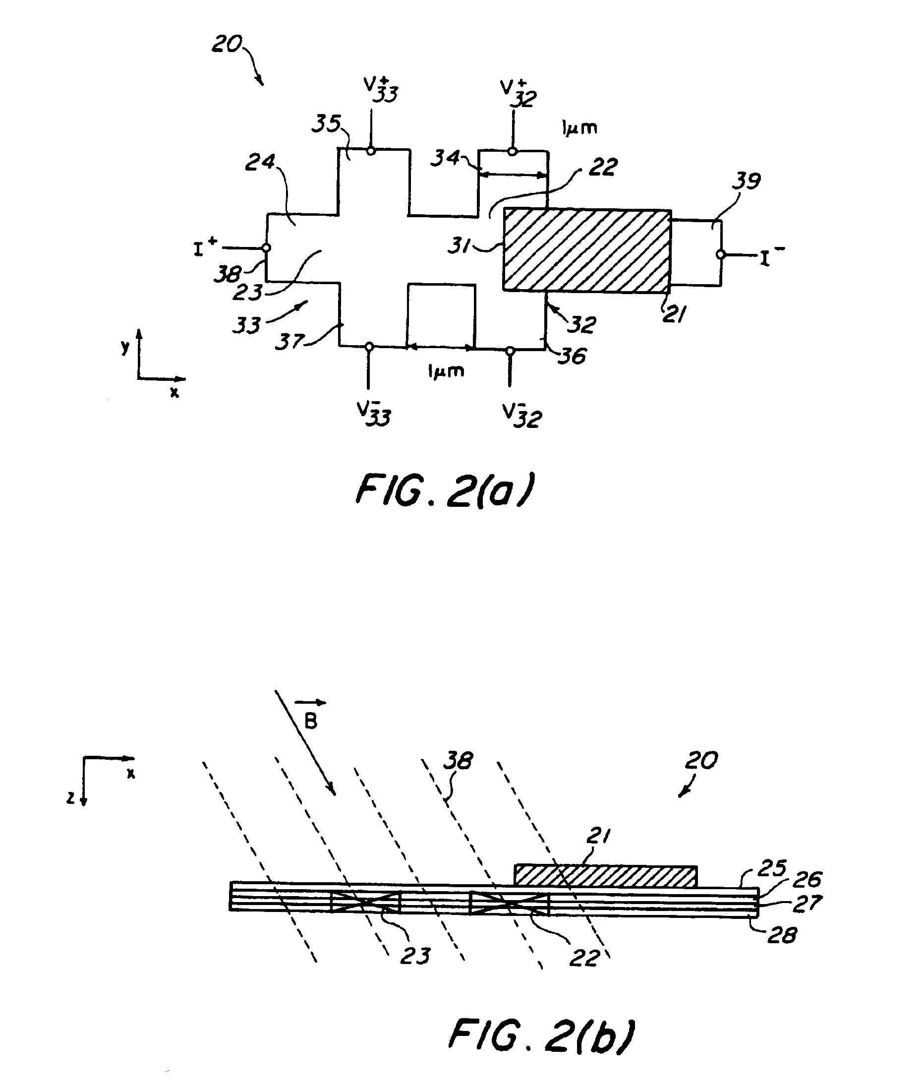
[0043]The basic device structure for a modified hybrid Hall device 20 that measures two vector field components is depicted in FIGS. 2(a) and 2(b). A standard Hall plate 24 is fabricated using conventional techniques known in the art to form two Hall crosses 22, 23, which are adapted to function as two Hall sensors generally denoted as 32, 33. The Hall crosses 22, 23, each have a first arm 34, 35 and a second arm 36, 37, respectively.

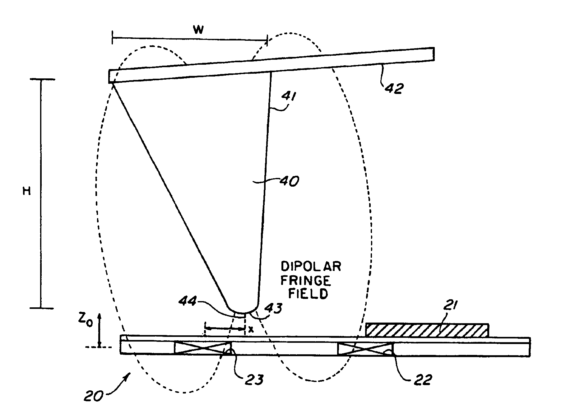
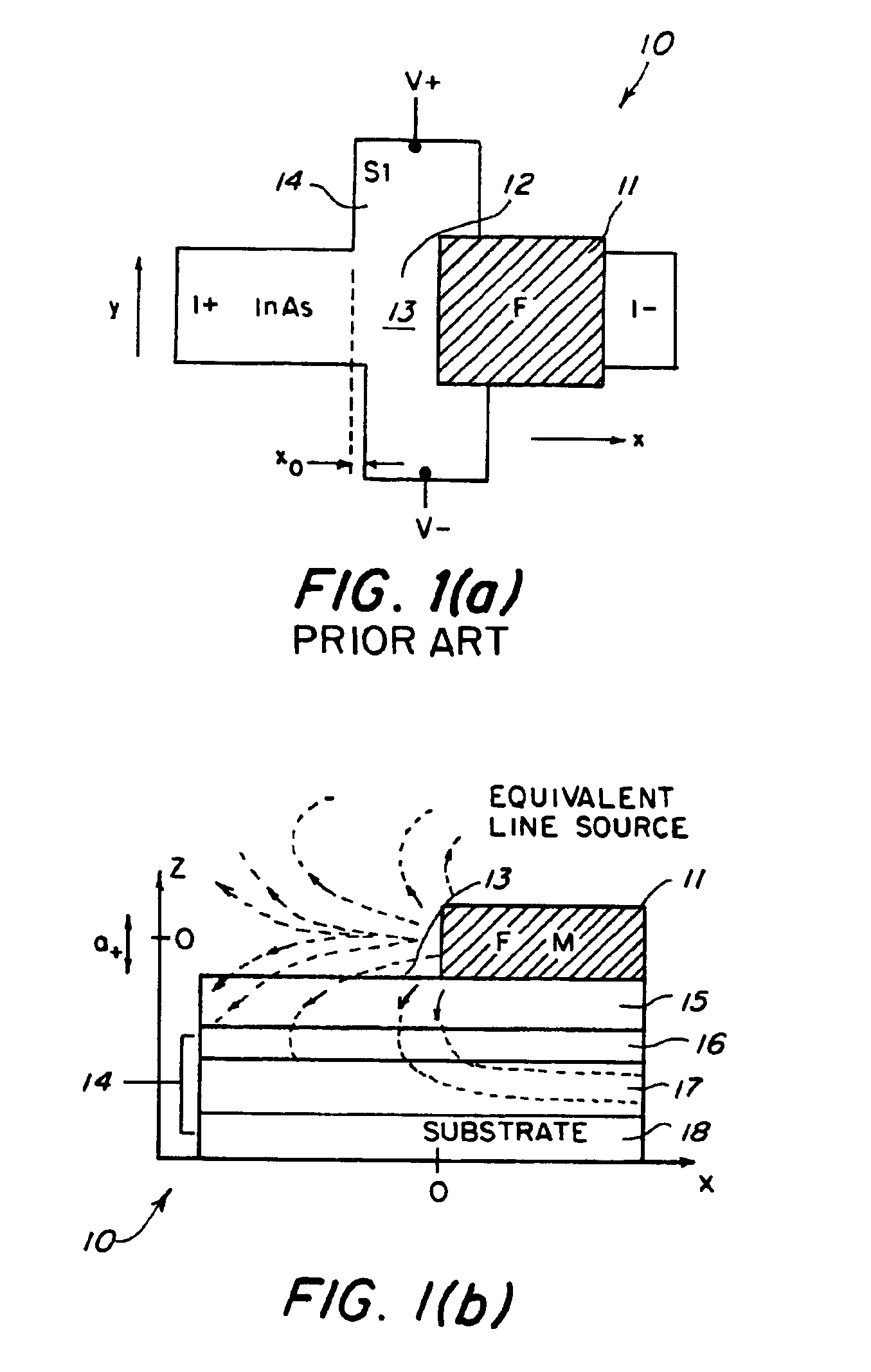
[0044]The Hall cross 22 is located in close proximity to Hall cross 23 and is formed in a manner consistent with that in the prior art Hall sensor 10 of FIG. 1. A thin, microstructured ferromagnetic film 21 is fabricated over the Hall cross 22 and positioned such that edge 31 of the ferromagnetic film 21 is over the central region of the Hall cross 22 and a fringe magnetic field emanates or projects from the edge 31 of the ferromagnetic film 21. The ferromagnetic film 21 is electrically isolated from the surface of Hall plate 24 by a thin insulating lay...


PUM


Abstract

A modified hybrid Hall effect device is provided which is the combination of a conventional Hall effect device and a second Hall effect device having a Hall plate coupled to a ferromagnetic layer. The hybrid Hall effect device can be used to determine the independent magnetic field vector components comprising a vector magnetic field, such as for determining the {circumflex over (x)} and the {circumflex over (z)} components of a magnetic field, or for measuring the total magnitude of a vector magnetic field of any orientation. The modified Hall Effect device can be adapted for use as a magnetic field sensor for the detection of macroscopic objects that have associated magnetic fields, or for microscopic objects that have been tagged by microscopic magnetic particles. In one specific form, a plurality of hybrid Hall devices are electrically connected together to form an array in which a plurality of rows of hybrid Hall devices are electrically coupled to each other along a current axis, and the array is used for the detection of microscopic objects.

Description

CROSS REFERENCE TO RELATED APPLICATIONS[0001]This application is a divisional of application Ser. No. 10 / 287,876, filed Nov. 4, 2002, now issued as U.S. Pat. No. 6,800,913.FIELD OF THE INVENTION[0002]The present invention relates generally to a Hall Effect device, and, in particular, to a modified Hall effect device which is a hybrid combination of a first conventional Hall plate and a second conventional Hall plate coupled to a ferromagnetic layer.BACKGROUND OF THE INVENTION[0003]Several different types of devices are available for the measurement of magnetic fields. Examples that operate at room temperature include flux gate magnetometers and magnetoresistors. A third family of devices is one of the oldest commercial field sensors, the Hall plate. All of these devices share a common trait; they measure a scalar value of magnetic field that represents a single component of the vector field to be measured. The family of Hall devices includes dozens, if not hundreds, of variations, f...

Claims


Application Information

Patent Timeline
IPC IPC(8): G01R33/06G01R33/07G01B7/14G01Q60/54
CPCG01R33/07Y10S977/853Y10S977/865
Inventor JOHNSON, MARK B.MILLER, MICHAELBENNETT, BRIAN
Owner THE GOVERNMENT OF THE UNITED STATES OF AMERICA AS REPRESENTED BY THE SEC OF THE NAVY NAVAL RES LAB WASHINGTON
Why Eureka
Try Eureka