Bottom grate of a crusher or drum chipper and method of producing the bottom grate

a technology of crushers and drums, which is applied in the field of bottom grates of crushers or drum chips, can solve the problems of large damage, large wear of bottom grates, and the need for wider-scale welding operations, and achieves the effect of reducing the service life of the bottom grate, facilitating and accelerating maintenance and repair, and reducing the number of blades

Inactive Publication Date: 2017-07-25
ANDRIZ OY
View PDF9 Cites 0 Cited by
  • Summary
  • Abstract
  • Description
  • Claims
  • Application Information

AI Technical Summary

Benefits of technology

[0018]The solution according to the invention offers clear advantages compared to prior art, in view of both maintenance and production.
[0019]A remarkable improvement in the solution according to the invention is seen in significantly easier and quicker maintenance and repair. The novel bottom grate construction that can be mounted and opened enables easy replacement of even individual blades. Damage caused by occasional excessively hard pieces is usually directed to only a certain blade or blade piece or support element or some of them. The repair measure now required is the replacement of damaged parts only instead of replacing the whole grate, whereby the service life of the bottom grate is significantly increased.
[0020]An advantage of the arrangement worth mentioning comes from the numerous various possibilities for improving the usability of the bottom grate blades. According to an embodiment, the blades or blade pieces can be arranged turnable. In other words, a blade may be symmetric in at least one direction and have more than one cutting edge on the opposing sides of the blade. The service life of an individual blade can be doubled by using both cutting edges formed in the opposite edges of the blade. If the shape of the blade is substantially rectangular, the blade may have up to four cutting edges. This provides relevant cost savings.
[0021]If the blade is divided into several blade parts, the blade parts are so small and the production volume is so high that their serial production is affordable to be automated. When there is uneven wear or damages in only one or some parts of the full length of the combined blade, only relevant blade pieces need to be replaced or turned instead of changing long and expensive full length blades.
[0022]The bottom grate construction according to the invention also enables reuse of the blades. In other words, the blades can be made re-groundable so that one piece of blade can be used several times. However, the blades can still be repaired by welding.
[0023]Also other significant advantages are obtained with the invention, such as lowered production costs of the bottom grate according to the invention. A bottom grate compiled by bolting is more economical in view of production technique than a structure fabricated by welding. Separate blade pieces, such as also other parts of the bottom grate are easier to handle and their production and repair in series can be automated.
[0024]A further significant advantage is that if required, the final assembly of the bottom grate can be performed at the place of mounting. All transportations can be carried out in disassembled form, if needed. Also, the precision fitting of the bottom grate with the rotor can be performed at site quickly and precisely. The structure can always be disassembled to the required extent and fitted e.g. by means of adjusting pieces to a desired exact form and dimensioning.
[0025]On the other hand, during repair the structure of the bottom grate “remains in form”, since no welding energy is directed to the structure, which would cause deformations. Adjusting the clearance between the blades and rotor is avoided, which results in more uniform shredding and decreased energy consumption. More advantages offered by the invention are disclosed in the following description of embodiments of the invention.

Problems solved by technology

The bottom grate and the blades are exposed to wearing during operation.
Additionally, major damages are caused occasionally by too hard pieces that now and then may remain in the material to be comminuted or chipped.
In case of major damages, even wider-scale welding operations may be required.
This kind of repairing is laborious and time consuming and further leads to extended shut-down periods.
This, in turn, leads to over-welding and further extra work, such as levelling and additional grinding.
If bigger metal or other excessively hard particles enter the crusher with the material to be treated, a welded bottom grate is typically twisted unusable and thus needs to be scrapped.
Thus, the operational life of the grate can be very short.

Method used


Image

  • Bottom grate of a crusher or drum chipper and method of producing the bottom grate
  • Bottom grate of a crusher or drum chipper and method of producing the bottom grate
  • Bottom grate of a crusher or drum chipper and method of producing the bottom grate

Examples


Embodiment Construction

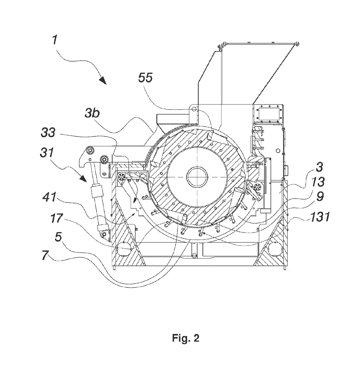
[0032]FIGS. 1 and 2 illustrates a crusher 1 for chipping and / or comminuting material. The crusher 1 has a stationary body 3 provided with counter blades (not shown) and their position and distance are adapted in relation to a rotor 5 mounted rotatably on bearings inside the body. Crushing or cutting blades 55 are arranged on the outer circumference of the rotor 5.

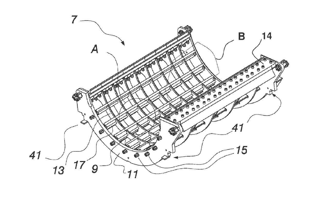
[0033]A bottom grate 7 in accordance with the invention is mounted below the rotor 5. The bottom grate 7 is curved following the shape of the rotor 5. There are end support elements 11 and intermediate support elements 13 in a direction perpendicular to rotor 5 axis supporting the blades 9 substantially parallel to the rotor axis. Openings 91 are formed between them for exiting the treated material.

[0034]FIGS. 2, 3a, 3b and 3c illustrates in more detail a bottom grate 7 for a crusher according to the invention and the fitting of the grate. Thus, main components thereof comprise end support elements 11 and intermediate suppo...


PUM

PropertyMeasurementUnit
tensionaaaaaaaaaa
compressive forceaaaaaaaaaa
bow shapeaaaaaaaaaa

Abstract

A bottom grate for a crusher for chipping or comminuting material which includes: support ribs each substantially perpendicular to the rotational axis of the crusher; grate blades mounted to the support ribs and substantially parallel to the rotational axis, wherein the grate blades are releasably mounted to the support ribs and the grate blades each have a cutting edge proximate to a cutting or crushing rotor in the crusher; pulling members extending between two of the support members, wherein the pulling members are in tension and the tension in the pulling members binds the blades in the support members.

Description

RELATED APPLICATIONS[0001]This application is the U.S. national phase of International Application No. PCT / FI2012 / 050434 filed 4 May 2012 which designated the U.S. and claims priority to FI 20115439 filed 6 May 2011, the entire contents these applications are incorporated by reference.BACKGROUND OF THE INVENTION[0002]The invention relates to a bottom grate of a crusher or drum chipper for chipping and / or comminuting material comprising a stationary body, a rotor mounted rotatably with bearings, the outer circumference of which is provided with crushing and / or cutting blades, and below the rotor with a curved bottom grate conforming to the shape of the rotor, said bottom grate having curved support elements in a direction substantially perpendicular to the axis of the rotor and blades substantially parallel to the direction of the axis. The invention also relates to a method of producing the bottom grate according to the invention.[0003]Most preferably the invention relates to a crus...

Claims


Application Information

Patent Timeline
Patent Type & Authority Patents(United States)
IPC IPC(8): B02C23/00B02C23/16B02C13/284
CPCB02C13/284B02C23/16Y10T29/49826
Inventor KALJUNEN, MARKKUKOKKO, PEKKA
Owner ANDRIZ OY
Why Eureka
Try Eureka