
Transverse mechanical translator with ferrofluid support

a technology of ferrofluid and mechanical translator, which is applied in the direction of magnets, magnetic liquids, magnetic bodies, etc., can solve the problems of cumbersome mechanism that controls the motion of the low friction system, and affecting the translation accuracy of the translation

Inactive Publication Date: 2005-07-12
INNOVATIVE TECH LICENSING
View PDF27 Cites 6 Cited by
  • Summary
  • Abstract
  • Description
  • Claims
  • Application Information

AI Technical Summary

Benefits of technology

"The present invention is a mechanical translator system with a low friction and a novel ferrofluid composition as a lubricant. The translator includes a moveable magnet that is arranged to carry a load and is disposed for movement on a substrate. The magnetic axis is generally transverse to the substrate, such that its magnetic field has a maximum density adjacent the substrate. A ferrofluid lubricant is preferably provided between the magnet and substrate. The resulting coefficient of static friction has been found to be in the approximate range of 0.0008-0.0012. A plurality of moveable magnets can be used to support a platform upon which a load can be placed, or which itself can comprise a load. A ferrofluid lubricant is provided between the magnets and substrate for ultra low frictional movement. The moveable magnets can be controlled by a controller formed from a magnetic material outside the vacuum chamber, on the opposite side of the floor from the moveable magnets, to achieve uniform deposition, eliminating the need for the cumbersome control equipment and its mechanical communication through the vacuum chamber that were previously required."

Problems solved by technology

Low friction systems can have other problems.
The mechanism that controls this motion is cumbersome, consisting of gears, chains, and both rotary and translational motion vacuum feedthroughs.
Traditional lubricants employed to assist movement of a load bearing mechanism on a substrate, while considerably reducing the frictional forces resisting motion, still involve a considerable amount of friction.

Method used


Image

  • Transverse mechanical translator with ferrofluid support
  • Transverse mechanical translator with ferrofluid support
  • Transverse mechanical translator with ferrofluid support

Examples


Embodiment Construction

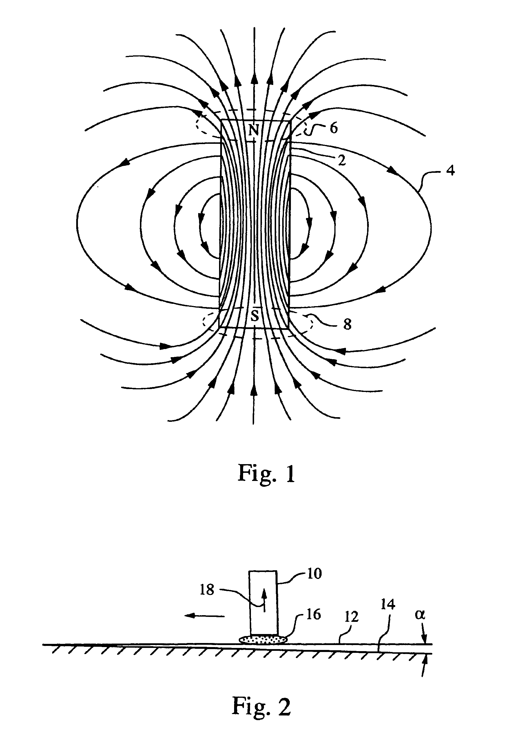
[0017]FIG. 1 illustrates a bar magnet 2 and its associated magnetic field lines 4. As is well known, the field lines radiate out mostly from the magnet's north pole, and loop around to return to the magnet's south pole. The greatest magnetic field concentrations external to the magnet are at its opposite poles, and it is in these regions that a ferrofluid will tend to accumulate when the ferrofluid is presented to the magnet. The ferrofluid concentration formed at the opposite ends of the magnet, indicated by dashed ovals 6 and 8 around the north and south magnet poles, respectively, can be used as bearings to provide a lubricated movement of the magnet along a surface. Ferrofluid bearings would also tend to form at the opposite ends of an electro-magnet as well as a permanent magnet.

[0018]Referring now to FIG. 2, a magnet 10 is shown supported on a substrate 12, which in turn is on a horizontal support surface 14. A ferrofluid bearing 16 provides an ultra low friction interface bet...


PUM

PropertyMeasurementUnit
sizeaaaaaaaaaa
sizeaaaaaaaaaa
angleaaaaaaaaaa

Abstract

A mechanical translator includes at least one magnet that is disposed on a substrate to carry a load and has a magnetic axis generally transverse to the substrate, establishing a magnetic field with maximum external density adjacent the substrate. An ultra low friction interface is obtained with ferrofluid bearings, such as a light mineral oil medium mixed with isoparaffinic acid, which establish a critical angle of displacement from a horizontal static position of less than 1 degree, and preferably less than 10 minutes. A controller of magnetic material can be placed on the opposite side of the substrate to control the movement of the magnets.

Description

RELATED APPLICATION[0001]This application is a continuation of Ser. No. 10 / 741,667, filed Dec. 19, 2003, now U.S. Pat. No. 6,833,780, which in turn is a divisional of Ser. No. 10 / 078,132, filed Feb. 19, 2002 and now abandoned, and claims the benefit of both prior applications.BACKGROUND OF THE INVENTION[0002]1. Field of the Invention[0003]This invention relates to magnetic-based mechanical translators, and more particularly to mechanical translators with ferrofluid bearings.[0004]2. Description of the Related Art[0005]Ferrofluids are dispersions of finely divided magnetic or magnetizable particles, generally ranging between about 30 and 150 Angstroms in size, dispersed in a liquid carrier. The magnetic particles are typically covered with surfactants or a dispersing agent. The surfactants assure a permanent distance between the magnetic particles to overcome the forces of attraction caused by Van der Waal forces and magnetic interaction, and also provide a chemical composition on th...

Claims


Application Information

Patent Timeline
Patent Type & Authority Patents(United States)
IPC IPC(8): C10M171/06C10M171/00F16C33/04F16C33/10F16C29/00F16C29/02H01F1/44H02K7/09H02K49/00H02K49/10
CPCC10M171/06F16C29/02F16C32/0637F16C33/1035H01F1/44C10M2201/062C10M2203/1006C10M2207/12C10N2210/08C10N2220/02C10N2220/082C10N2230/06C10N2240/02C10N2250/12H02K7/09H02K49/10H02K2201/18C10N2010/14C10N2020/01C10N2020/06C10N2030/06C10N2040/02C10N2050/015C10N2010/16
Inventor CHEUNG, JEFFREY T.
Owner INNOVATIVE TECH LICENSING
Learn More