
Method and a device for supplying fuel to a combustion chamber

a technology of combustion chamber and fuel supply, which is applied in the direction of engine ignition, engine starter, lighting and heating apparatus, etc., can solve the problems of difficult control of the flow to the main and pilot injector, and achieve the effect of reducing emissions and improving safety against extinguishing

Inactive Publication Date: 2005-07-12
VOLVO AERO CORP
View PDF10 Cites 10 Cited by
  • Summary
  • Abstract
  • Description
  • Claims
  • Application Information

AI Technical Summary

Benefits of technology

[0009]A first objective of the invention is to make available a method for supplying fuel to a combustion chamber which permits more exact control of the flow of fuel than possible using known systems. The aim in particular is to reduce the emissions compared to the known systems and to achieve improved safety against extinguishment of the combustion chamber at a low load operating state.
[0010]This objective is achieved by the fact that a second flow of fuel, which is substantially smaller than the first flow of fuel, is supplied to the pilot injector in order to achieve a specific operating state, distinct from start-up, via a second regulator valve that is designed to regulate a substantially smaller flow than the first regulator valve. In other words, a small valve (the second regulator valve) is used for regulating a small flow, and a large valve (the first regulator valve) is used for regulating a large flow to the pilot injector. This creates the conditions for achieving a regulation of the flow to the pilot injector that is more exact than in known systems. By virtue of this method, the supply of the fuel can be accurately controlled especially at transitions between different operating states.
[0011]According to a preferred embodiment, the first regulator valve is arranged to convey the first flow of fuel to the main injector when the combustion chamber is intended to be driven at an intermediate or high load state. At this intermediate or high load state, the pilot injector is thus supplied with a small flow of fuel via the second regulator valve. The first regulator valve is thus used to control a large flow of fuel to the pilot injector in a certain operating state and to the main injectors in another operating state. Controlling the supply of fuel in this way makes it possible to create the conditions for a cost-effective and space-saving fuel supply device.
[0013]A second objective of the invention is to provide a device for supplying fuel to a combustion chamber creating the conditions for more exact control of the flow of fuel than previously available. The aim, in particular, is to be able to further reduce the emissions and to achieve improved safety against extinguishment of the combustion chamber at a low load operating state.

Problems solved by technology

With this arrangement, however, it has been found difficult to control the flows to the main and pilot injectors in an exact way which, on one hand, prevents extinguishment of the combustion chamber and, on the other hand, ensures that emissions, such as CO, NOx, and uncombusted hydrocarbons, are kept to a low level.

Method used


Image

  • Method and a device for supplying fuel to a combustion chamber
  • Method and a device for supplying fuel to a combustion chamber
  • Method and a device for supplying fuel to a combustion chamber

Examples


Embodiment Construction

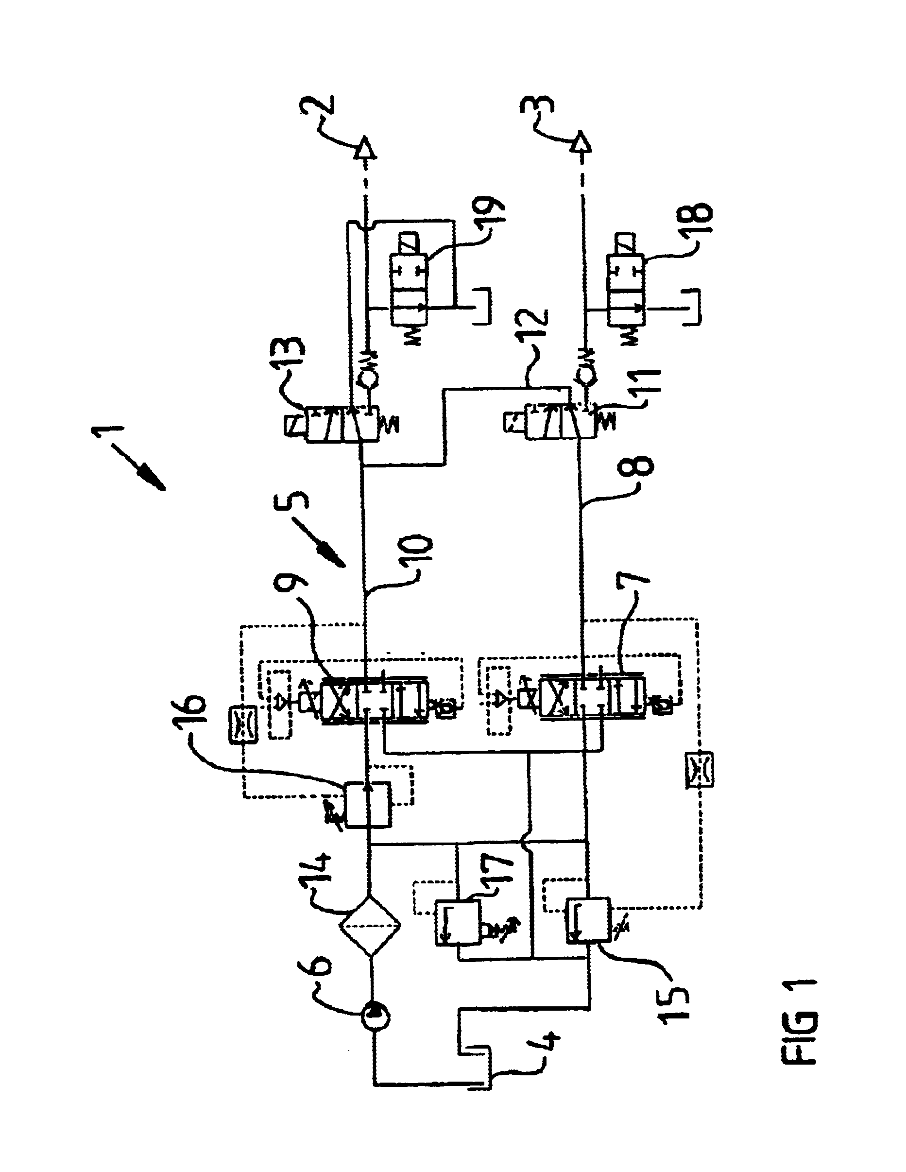
[0018]FIG. 1 illustrates a preferred embodiment of a device 1 for supplying fuel to a combustion chamber of a gas turbine. The combustion chamber is of the low-emission type and has a centrally arranged pilot injector and a plurality of main injectors arranged thereabout. In FIG. 1, the pilot injector 2 and the main injectors 3 are illustrated schematically.

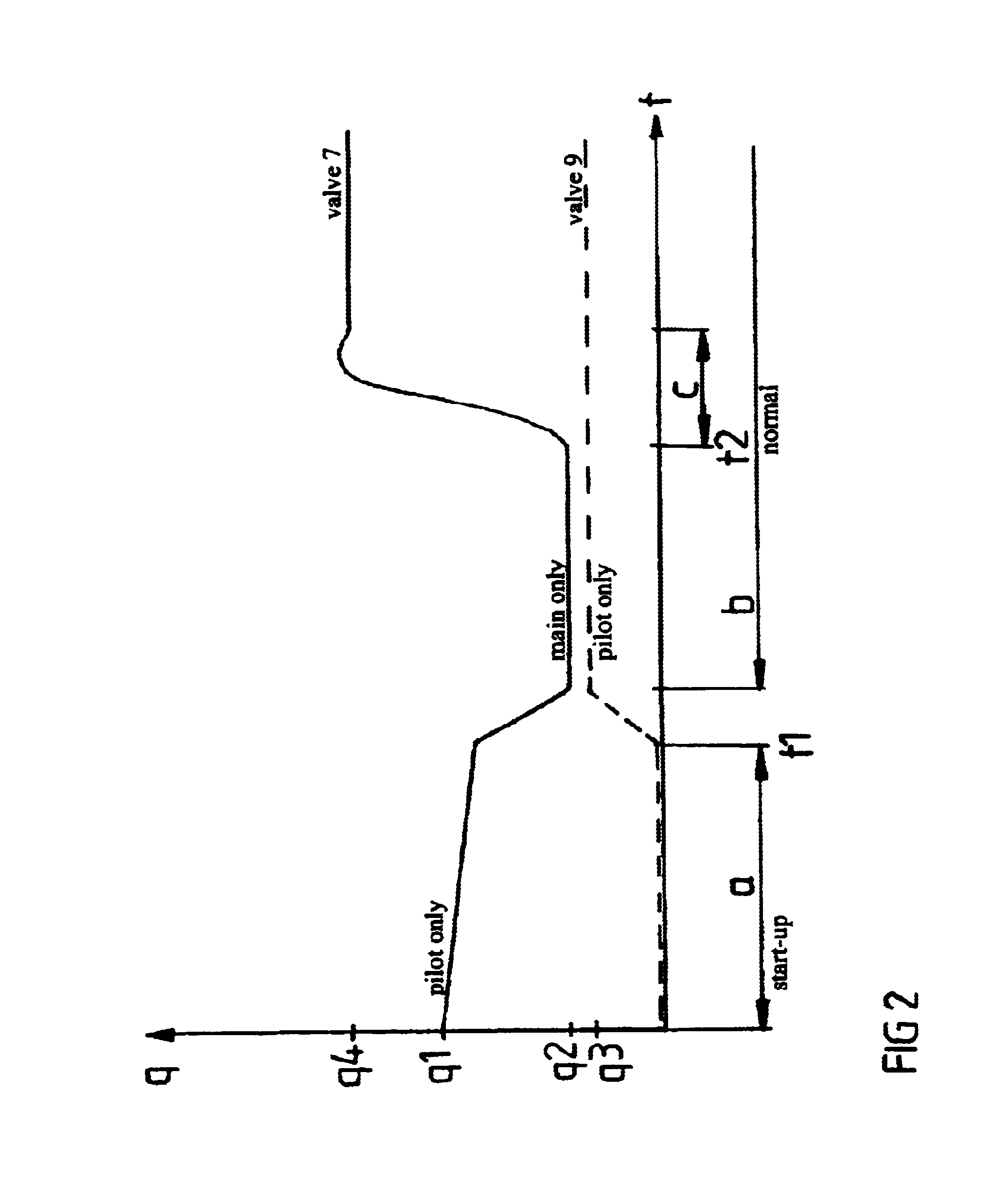
[0019]The size of the flows of fuel supplied to the injectors 2, 3 depends on the intended operating state of the incorporating engine. When starting up a cold engine, and possibly at a low load state, a relatively large flow of fuel is supplied to the pilot injector and essentially no fuel is supplied to the main injectors. At the intermediate and high load states, by contrast, the pilot injector is supplied with a small flow of fuel and the main injectors are supplied with a large flow of fuel. In the latter case, the pilot injector is used as a safety against the system extinguishing. The difference in the size of the flows of...


PUM


Abstract

Method and device (1) for supplying fuel to a combustion chamber that includes at least one main injector (3) and at least one pilot injector (2). The device includes a fuel tank (4), a line system (5) coupled from the fuel tank to the injectors (2, 3), a pump (6) for pumping fuel from the tank to the injectors, and a first regulator valve (7) for regulating the flow of fuel in a first line (8) in the system which is connected to the pilot injector (2). The device further includes a second regulator valve (9) for regulating the flow of fuel through a second line (10) in the system, which is connected to the pilot injector (2). The second regulator valve (9) is designed to regulate a substantially smaller flow than the first regulator valve (7).

Description

CROSS REFERENCE TO RELATED APPLICATIONS[0001]This application is a continuation patent application of International Application No. PCT / SE01 / 02803 filed 17 Dec. 2001 now abandoned, which was published in English pursuant to Article 21(2) of the Patent Cooperation Treaty, and which claims priority to Swedish Application No. 0100369-8 filed 6 Feb. 2001. Said applications are expressly incorporated herein by reference in their entireties.BACKGROUND OF INVENTION[0002]1. Field of the Invention[0003]The present invention relates to a method for supplying fuel to a combustion chamber which comprises (includes, but is not limited to) at least one main injector and at least one pilot injector, with a first flow of fuel being supplied to the pilot injector during start-up of the combustion chamber via a first regulator valve.[0004]The invention also relates to a device for supplying fuel to a combustion chamber which comprises at least one main injector and at least one pilot injector. The de...

Claims


Application Information

Patent Timeline
Patent Type & Authority Patents(United States)
IPC IPC(8): F02C7/22F02C9/26F02C9/00F02C9/34F02C7/228F23K5/04F23K5/02F23N1/00
CPCF02C7/228F02C9/26F02C9/34F23K5/04F23N1/007F23D2900/00014F23D2900/00015F23N2027/02F23N2027/22F23N2227/22F23N2227/02
Inventor JONSSON, BERTIL
Owner VOLVO AERO CORP
Learn More