
High pressure discharge lamp and method of production therefor

a technology of high pressure discharge and discharge lamp, which is applied in the manufacture of electric discharge tube/lamp, cold cathode, electrode system, etc., can solve the problems of shortening the life of high pressure discharge lamps, leaking of gas or blowout of bulbs, etc., and achieves the inhibition of the halogen cycle by the remaining oxygen, the effect of reducing the luminance and reducing the size of the bulb

Inactive Publication Date: 2005-07-05
USHIO DENKI KK
View PDF23 Cites 0 Cited by
  • Summary
  • Abstract
  • Description
  • Claims
  • Application Information

AI Technical Summary

Benefits of technology

[0018]Another object of the present invention is to provide a long-life high pressure discharge lamp which, even after being used for a long time, has a low degree of blackening or decrease in luminance and is capable of preventing leakage of the contained gas or a blowout of the bulb, and a method for manufacturing such a high pressure discharge lamp.
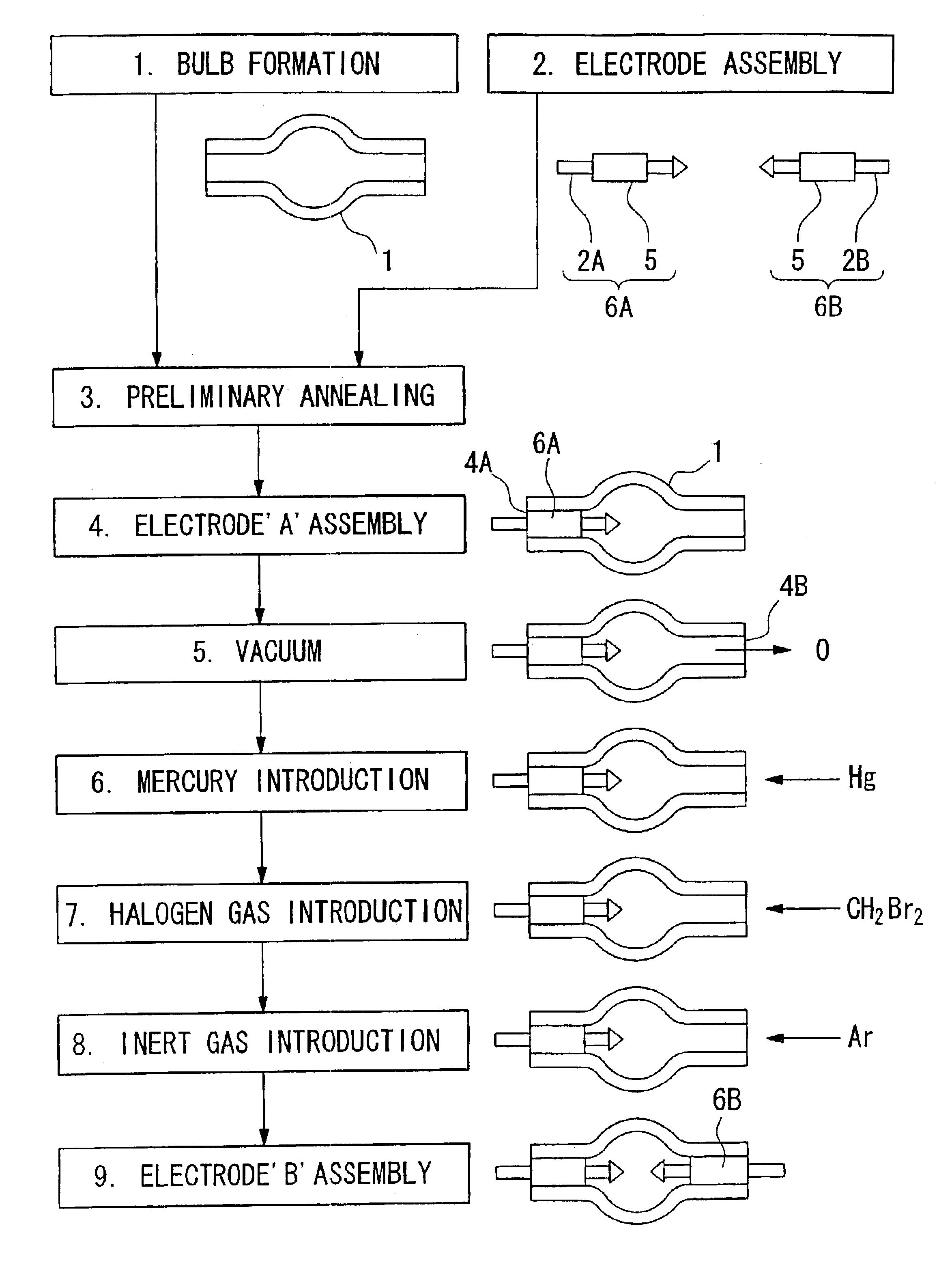
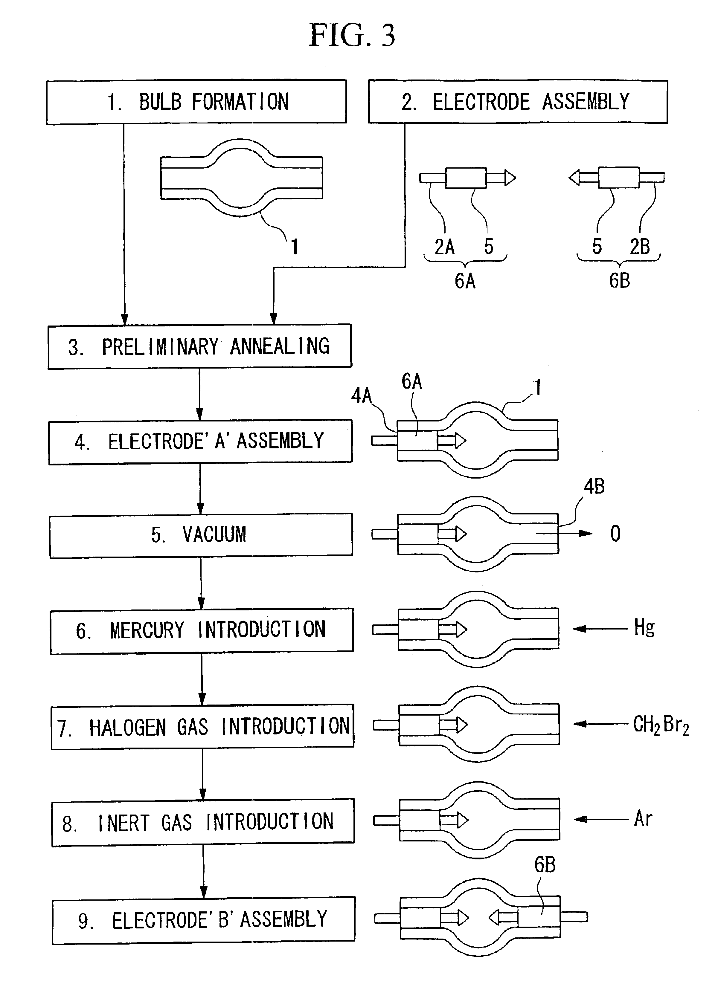
[0052]According to the above method, when the molybdenum foil is present between the electrode and the bulb, high airtightness of the high pressure discharge lamp may be maintained even for a repeated heat cycle. Also, if the quartz glass bulb and members that form the electrodes are preheated to a temperature in the range between about 1,000° C. and 2,000° C. in a vacuum, impurities which inhibit the halogen cycle, such as O2, CO, CO2, and H2O, that are initially absorbed or contained in the quartz glass bulb and members that form the electrodes may be removed, and hence, it becomes possible to further extend the service life of the high pressure discharge lamp according to an embodiment of the present invention. Moreover, if the insertion opening and the corresponding electrode are heated to a temperature in the range between about 1,000° C. and 2,000° C. in a vacuum when they are sealed, impurities in the atmosphere which inhibit the halogen cycle, such as O2, CO, CO2, and H2O, that are absorbed or contained in the insertion openings of the quartz glass bulb and the part of the electrodes the makes contact with the insertion openings may be removed, and hence, it becomes possible to further extend the service life of the high pressure discharge lamp according to an embodiment of the present invention.

Problems solved by technology

It was observed that an excessive amount of a halogen gas must be contained in the bulbs of the conventional high pressure discharge lamps for the reason explained above, and this shortens the life of the high pressure discharge lamps.
It was also discovered that tungsten molecules vaporized by the discharge under high temperature are ionized and damage the electrode by sputtering the electrode itself, thereby causing a leaking of gas or a blowout of the bulb.

Method used


Image

  • High pressure discharge lamp and method of production therefor
  • High pressure discharge lamp and method of production therefor
  • High pressure discharge lamp and method of production therefor

Examples


embodiments 1-7

(Embodiments 1-7)

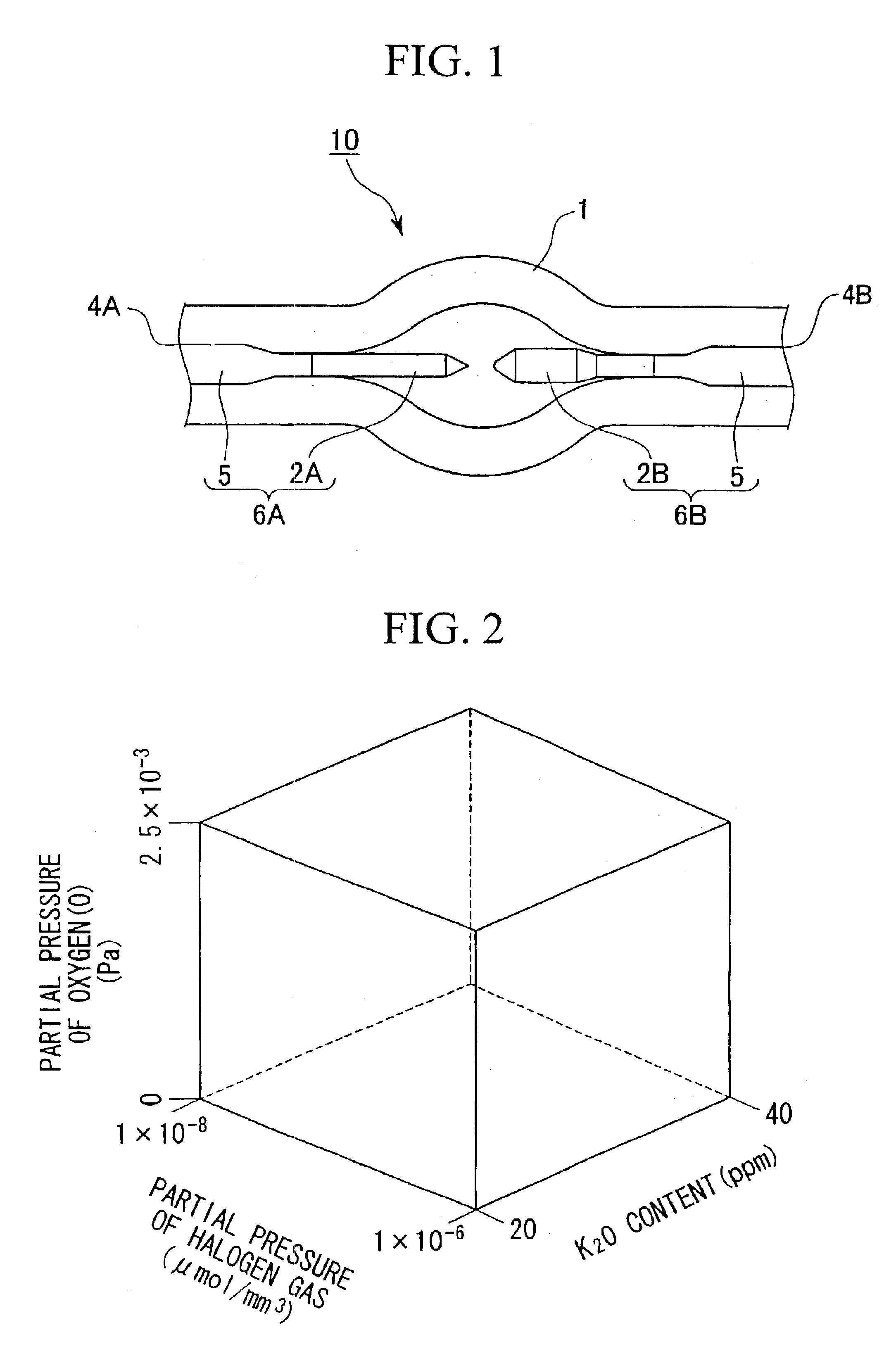
[0077]A high pressure discharge lamp of embodiments 1-7, respectively, according to the present invention was prepared by setting the partial pressure of oxygen (O) in the bulb 1, the partial pressure of halogen gas, and the amount of potassium oxide contained in the electrodes 2A and 2B, respectively, to the values shown in Table 1. In each of the embodiments, the amount of mercury sealed in the bulb 1 was 0.200 mg / mm3 and the amount of argon gas sealed in the bulb 1 was 5×10⁴ Pa.


PUM


Abstract

A high pressure discharge lamp includes a quartz glass bulb and a pair of electrodes. Each electrode of the pair of electrodes is disposed so as to be opposite the other in the quartz glass bulb. The quartz glass bulb of the high pressure discharge lamp contains at least mercury and a halogen gas which are airtightly sealed in the quartz glass bulb. The partial pressure of oxygen (O) in the quartz glass bulb is about 2.5×10⁻³ Pa or less and the partial pressure of the halogen gas in the quartz glass bulb is in the range between about 1×10⁻⁶ μmol / mm3 and 1×10⁻⁸ μmol / mm3. The pair of electrodes contain potassium oxide in the range between about 20 ppm and 40 ppm.

Description

[0001]This application is a division of Application Ser. No. 09 / 897,987, filed on Jul. 5, 2001, now U.S. Pat. No. 6,608,440, the entire contents of which are hereby incorporated by reference.BACKGROUND OF THE INVENTION[0002]1. Field of the Invention[0003]The present invention relates to a high pressure discharge lamp and to a method for producing the high pressure discharge lamp. More specifically, the present invention relates to a long-life high pressure discharge lamp which, even after being used for a long period of time, has a low degree of blackening and decrease in luminance, and which is capable of preventing leakage of a contained gas and blowout of the bulb, and to a method for manufacturing such a high pressure discharge lamp.[0004]2. Description of Related Art[0005]In general, a high pressure discharge lamp has a structure, for instance, as shown in FIG. 4. In the high pressure discharge lamp 110 shown in FIG. 4, each electrode of a pair of electrodes 102 and 102 made of...

Claims


Application Information

Patent Timeline
Patent Type & Authority Patents(United States)
IPC IPC(8): H01J61/00H01J61/06H01J61/12H01J61/073H01J61/82H01J9/32H01J9/385H01J9/395H01J61/20
CPCH01J61/0735H01J61/12H01J61/822
Inventor NISHIDA, KAZUHISAMAKINO, TOSHIMOTO
Owner USHIO DENKI KK
Learn More